Cisco IPSec Site to Site VPN
I've been playing around with route based IPSec VPN's lately and decided to write up a post on how to configure an IPSec VPN Tunnel between a Cisco router and a Palo Alto firewall. This will also work between two Cisco Routers or two PA firewalls but i only have one of each in my home lab so that's what i'm using. I'll be doing this lab using the following topology. R1 is a Cisco 860 series router and the firewall is a PA-220. While the Cisco 860 is a really old router, the commands for configuring the IPSec tunnels are identical on current routers. I know this because the configuration is the same on my 1100 series router running IOS-XE 17.9.
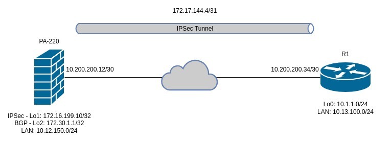
In the above topology, I will be configuring a very basic IPSec VPN tunnel between the two devices and will establish a BGP peering across the IPSec tunnels to advertise the required routes. The BGP peering will use a loopback interface on the PA firewall to peer with so will need to have eBGP multihop configured otherwise the BGP peering will not establish. The IPSec VPN configuration will be IKEv2 and will use PSK's for authentication. Lastly, I will also configure NAT overload (PAT) on the Cisco router tunnel interface so that all traffic traversing the tunnel, will be NAT'ed behind the tunnel IP address.
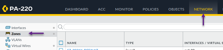
Let's start by configuring the Palo Alto firewall. Log into your PA and navigate to Network -> Zones and click Add to create a new VPN zone. I'm only creating one zone here but you can create as many as you need depending on your requirements.
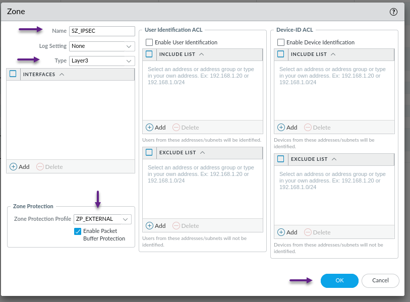
Give the zone a name and select the type as Layer 3. If you are using Zone Protection Profiles, you can also select that here too. Once done, click OK.
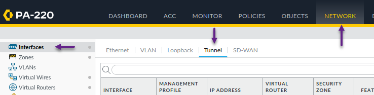
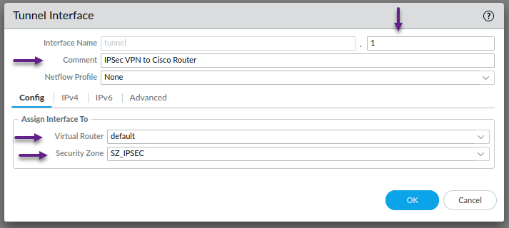
Next, create the tunnel interface. Navigate to Network -> Interfaces -> Tunnel and click Add to create a new interface.
On the Tunnel interface page, give the interface a number, and select the correct Virtual Router and the new Security Zone that you created in the previous step. Once done, click on the IPv4 tab.
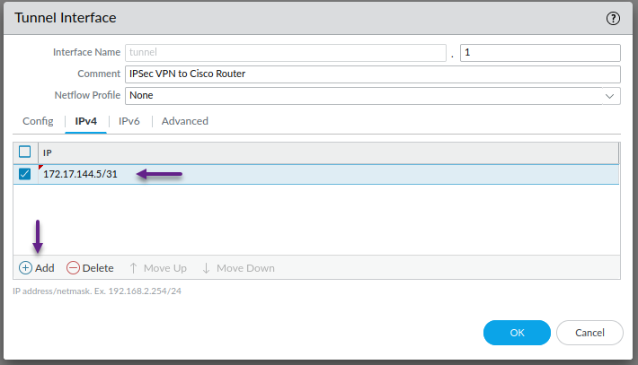
On the IPv4 tab, click Add and give the tunnel an IP address. Once done, click on the Advanced tab.
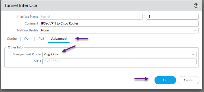
This is optional, but on the advanced tab, assign a management profile if you have one configured. I have one called Ping_Only which, you guessed it, only allows ping. Once done, click OK.
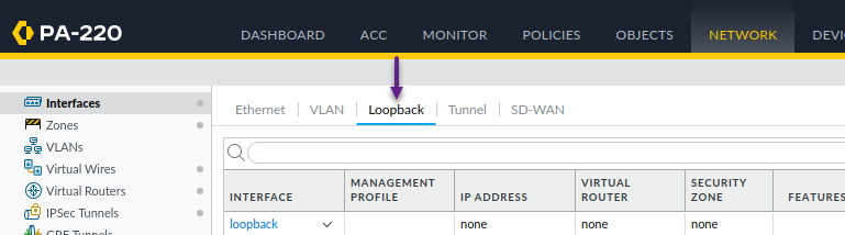
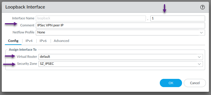
As i mentioned earlier, I'm using a loopback interface for both the termination address of the IPSec tunnel and the BGP peering on the PA so the next step is to create those interfaces. To create a loopback interface, navigate to Network -> Interfaces -> Loopback and click Add to create a new loopback interface.
In the Loopback Interface window, assign an interface number and configure the correct Virtual Router and Security Zone. Once done, click on the IPv4 tab.
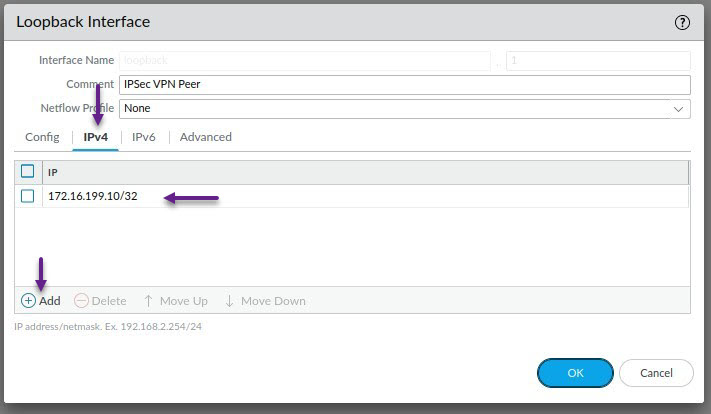
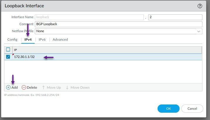
Click Add to configure an IPv4 address. Ensure that this address is a /32 as PA doesn't allow non /32 addresses on Loopbacks. Once the IP is configured, Click on the Advanced tab.
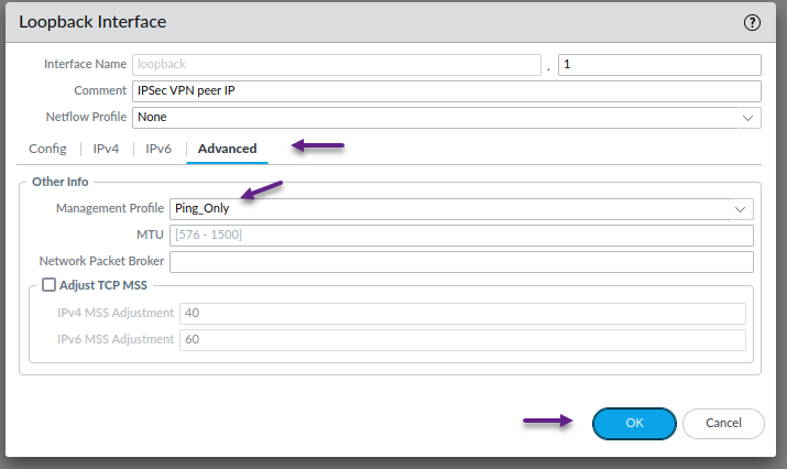
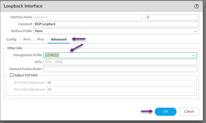
Once again, this is optional, but on the advanced tab, assign a management profile if you have one configured. Once done, click OK.
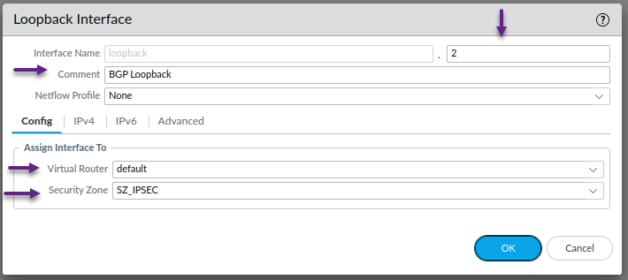
Repeat the above process for the second loopback interface that will be used for the BGP peering. Assign the Interface number, Virtual Router and Security Zone and click on the IPv4 tab.
Click Add to configure an IPv4 address and once done, click on the Advanced tab.
As always, this step is optional, but if you choose to, assign a Management Profile to the loopback interface and click OK when done.
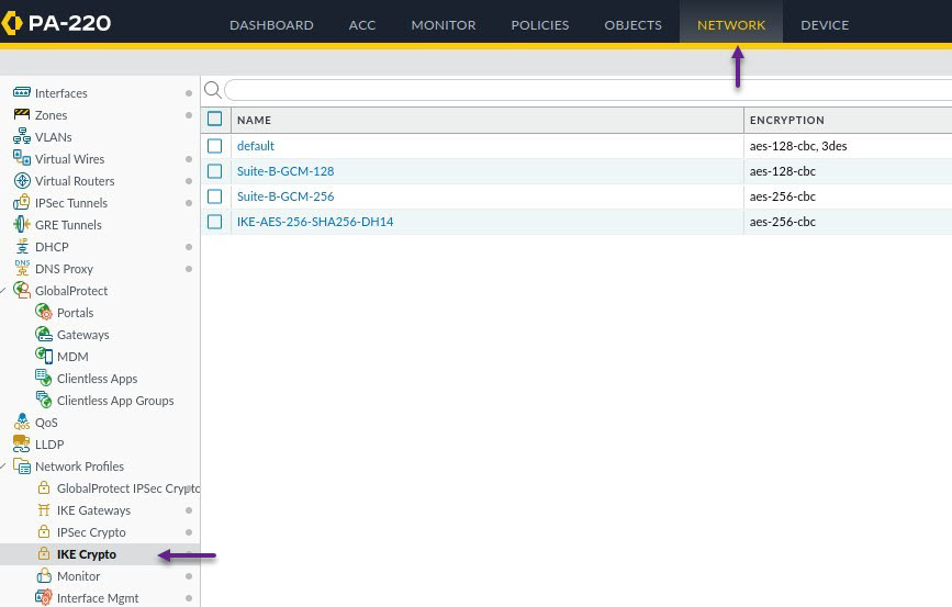
Okay, with the interfaces created, it's time to start configuring the IPSec tunnel settings. First, you'll need to create the IKE Crypto profile. To do that, navigate to Network -> Network Profiles -> IKE Crypto. On this page, you can either use the default pre-configured settings, or click Add to create your own profile.
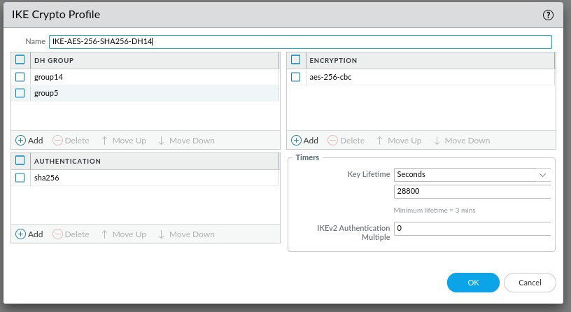
On the IKE Crypto Profile page, give the profile a name and select the DH, Encryption and Authentication settings you have chosen for your IPSec tunnel settings. Finally configure the correct Key Lifetime in seconds, minutes or hours and once done, click OK.
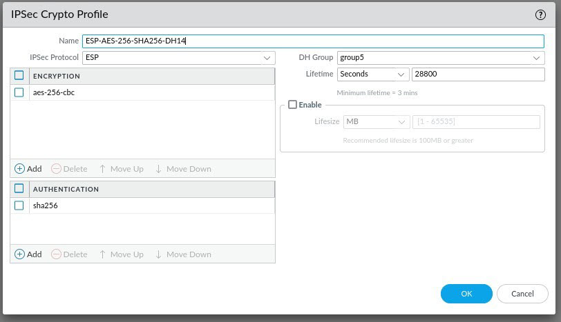
Next, you will need to create the IPSec Crypto configuration. Navigate to Network -> Network Profiles -> IPSec Crypto. Again, you can either use the default pre-configured settings here, or click Add to create your own.
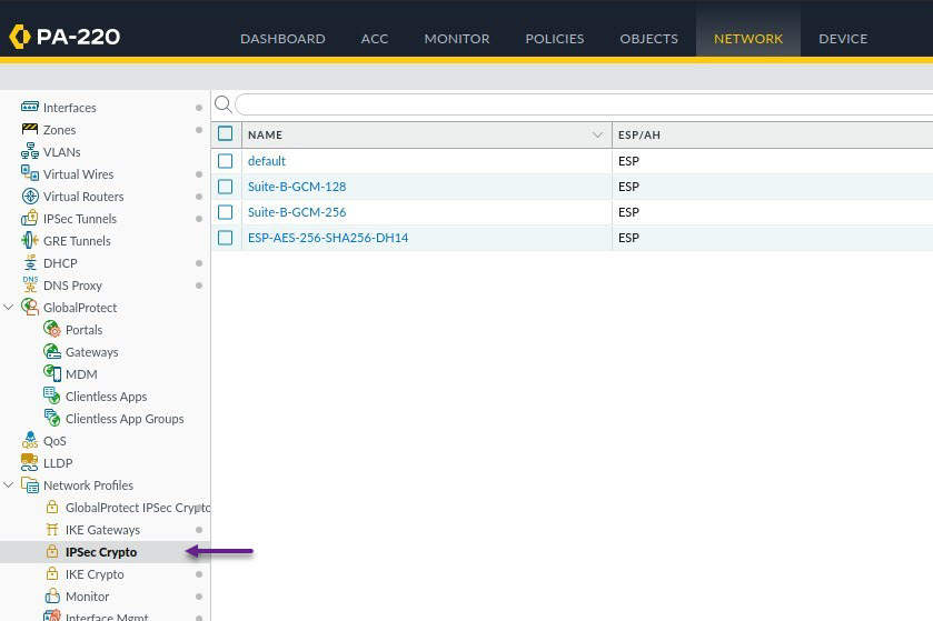
On the IPSec Crypto Profile page, provide a name, and IPSec Protocol type (This should almost always be ESP these days), then set the required Encryption, Authentication, DH Group and Lifetime settings. Once done, click OK.
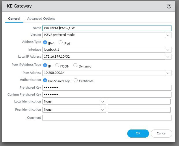
And the last step before configuring the IPSec Tunnel itself, is to create an IKE Gateway. This is where you specify your IKE VPN peer settings. Navigate to Network -> Network Profiles -> IKE Gateways and click Add to create a new IKE Gateway.

On the IKE Gateway page, configure all of the required IPSec details ensuring that you specify the correct Version, interface, Local IP address, Peer IP Address and Pre-Shared Key. You can leave the local identification and peer identification as None. Once you've configured the settings on the General tab, click on the Advanced Options tab.
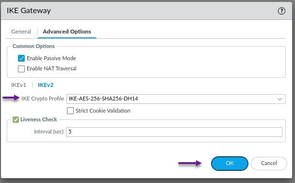
On the Advanced Options tab, select Enable Passive Mode (Unless you want the PA to attempt to establish the VPN session), set your IKEv1 Crypto Profile and then select IKEv2. (I would like to note here, that you may also need to enable NAT Traversal depending on your configuration. I have now tried this configuration on multiple firewalls and some required NAT-T and some didn't. It may be a PAN-OS setting i'm not sure)
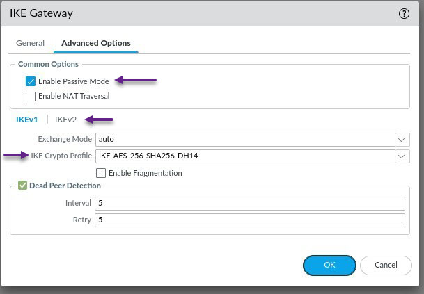
In the IKEv2 section select the IKE Crypto Profile that you created in the previous steps and click OK.
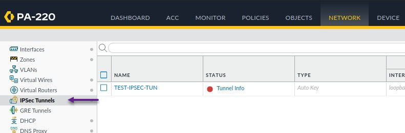
Finally, you can configure the IPSec Tunnel itself. To do that navigate to Nework -> IPSec Tunnels and click Add to create a new tunnel.
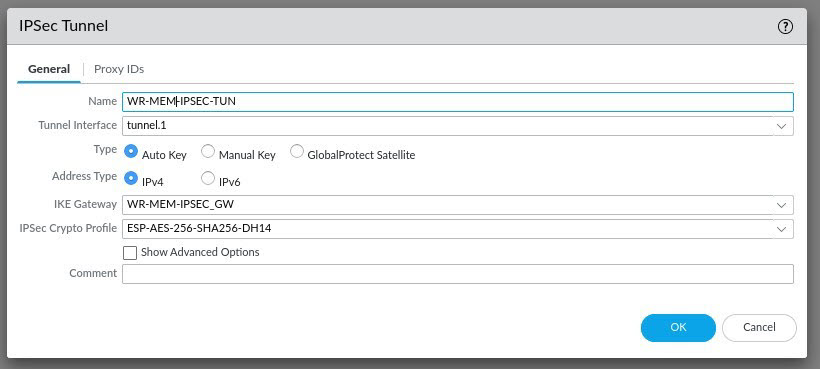
Under the general tab on the IPSec Tunnel page, configure a tunnel name and assign the tunnel interface you created in the earlier steps. Configure the correct IKE Gateway and IPSec Crypto Profile settings and then click OK. You don't need to worry about Proxy ID's for this routed based VPN solution, these are used for policy based VPN's and other things.
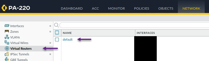
That's all that's required on the Palo Alto to get the VPN tunnel up and running, you can now commit those changes and either scroll down for the Cisco configuration or keep reading for the Palo Alto BGP configuration. If you've decided to keep reading, then let's get starting on the very bsaic BGP configuration. To enable and configure BGP, navigate to Network -> Virtual Routers and select the virtual router.
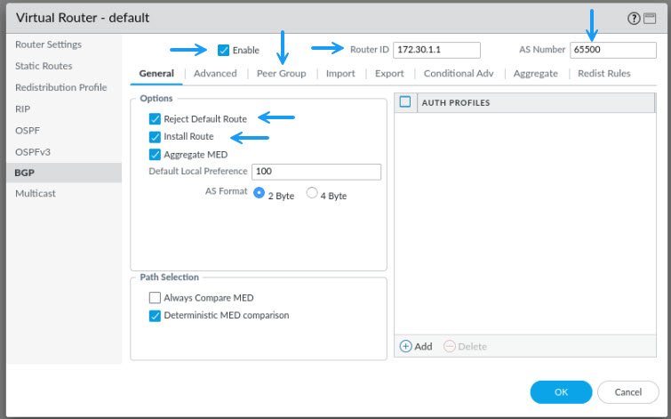
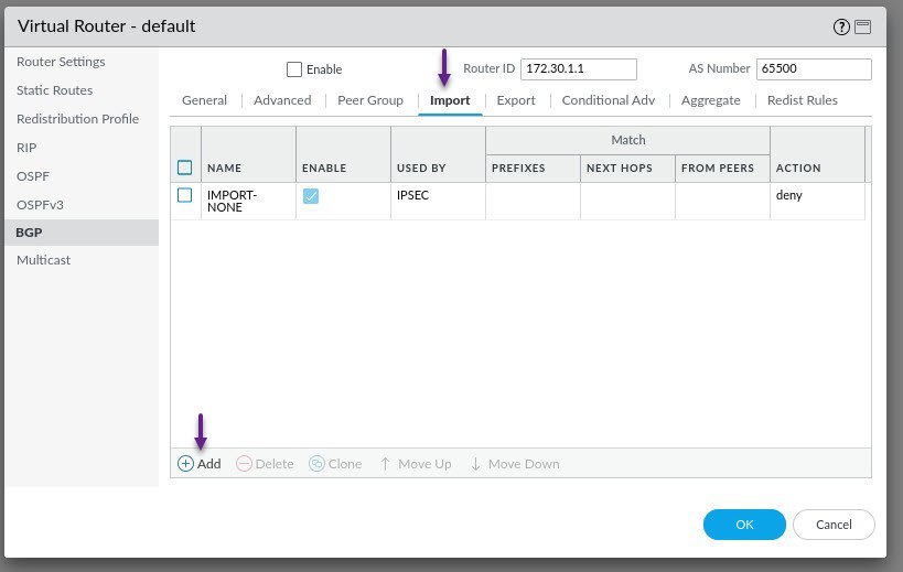
On the Virtual Router page, click on BGP on the left and click to Enable BGP. Configure the Router ID, AS Number, and enable Reject Default Route (Optional) and Install Route. Once done, click on the Peer Group tab.
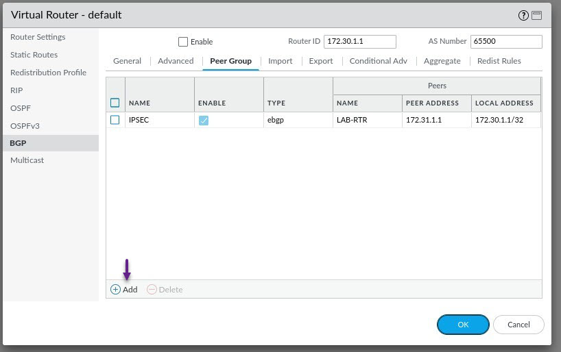
This is where you will configure your IPSec BGP neighbour peeer settings. Click on Add to create a new Peer Group.
On the Peer Group page, select Use Peer as Import Next Hop, and select Use Self as Export Next Hop. Once done, click Add to add a new peer.
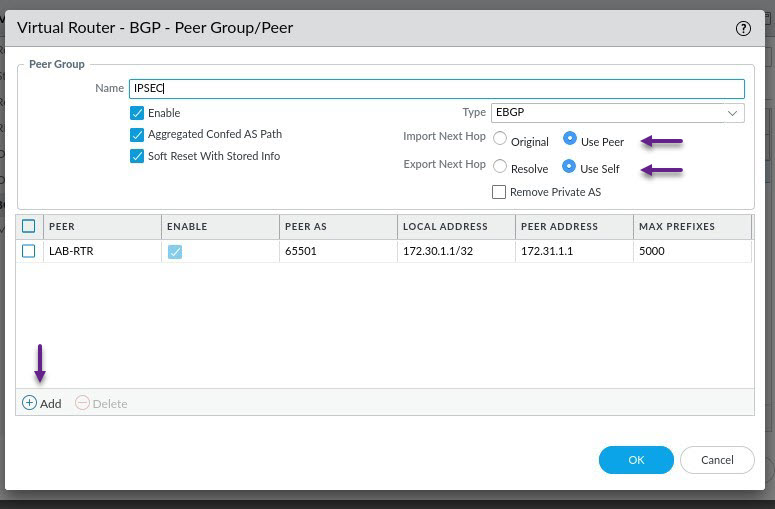
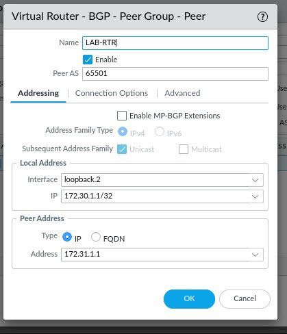
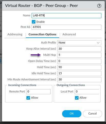
On the Peer page, give the VPN peer a name and specify the peers AS number. Under Local Address, assign the BGP loopback interface and IP address. Under Peer Address, select IP and configure the peer IP address. Once done, click on the Connection Options tab.
On the connection options tab, under Multi Hop, assign a value greater than 2. This is required in order to establish a BGP peering as we are using loopbacks on an eBGP peer. Once done, Click OK and then OK on all of the other windows until you get back to the Virtual Router window.
Back on the Virtual Router window, select Import and click Add to create an import profile. Click Add to create a new Import Rule.
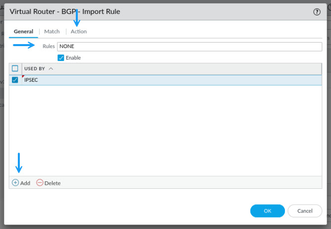
On the Import Rule page, give the rule a name, and click Add to select the peer group that you just created to apply the import profile to it. Once done, click on the Action tab.
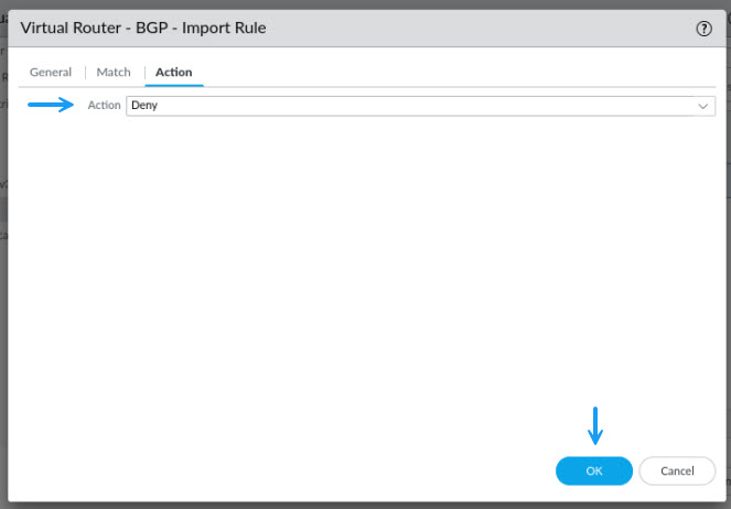
For this import profile, I'm denying all routes from being received from this peer group. This is because I don't need to be able to receive any as I will be NAT'ing all traffic on that peer. Once done, click OK.
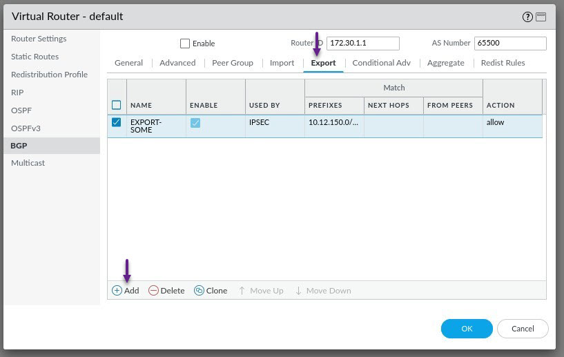
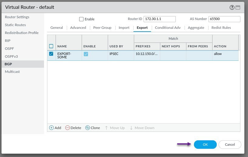
Now you will need to create an Export rule to allow the export of the 10.12.150.0/24 server subnet. Select the Export tab and click Add to create a new Export rule.
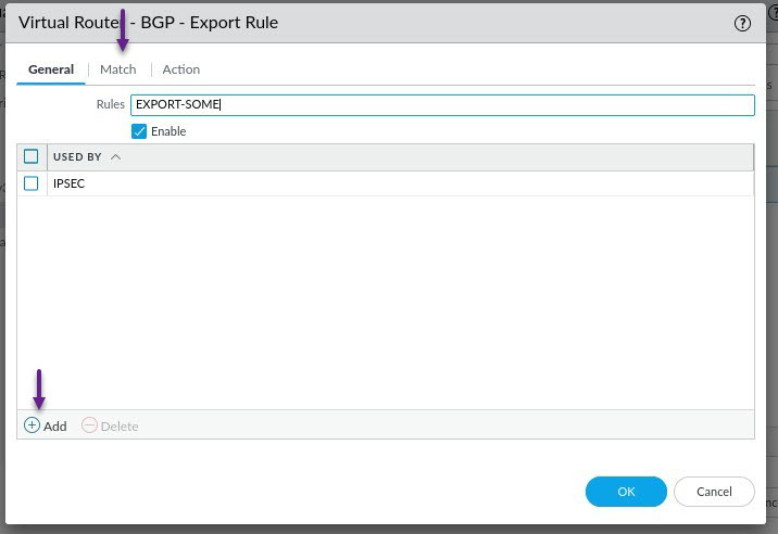
Give the rule a name and click Add to assign the peer group that you created to the Export rule. Once done, click on the Match tab.
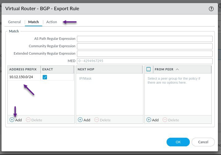
On this tab, you will specify the subnets or routes that you want to match that will be exported and advertised to the BGP peer. I'm only matching one specific subnet here which is the 10.12.150.0/4 subnet, and i'm matching exactly that /24 subnet. Once done, click on the Action tab.
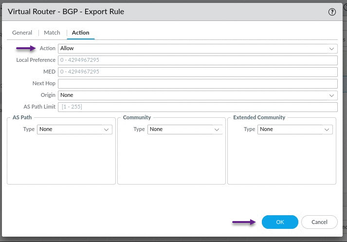
On the Action tab, select Allow and click OK.
That's all that needs to be configured on the Palo Alto for a very basic BGP configuration. Once you're done click OK and commit the changes to the firewall.
Once done and all changes have been commited to the firewall, remember that you will also need to create some policy rules to allow this traffic. Each configuration will differ with what rules are required, but make sure that you have allowed all required IPSec, IKEv2, isakmp and esp traffic and allow BGP over the VPN zones as well as any other traffic that should be permitted between your VPN zone and server zones.
Now let's take a look at the configuration of an IPSec tunnel on the Cisco router. My lab router is a Cisco 860 series, but as I mentioned in the beginning of this post, the configuration is pretty much the same on other platforms as well. In fact I was able to copy any past this exact config (Other than interface changes) onto a Cisco 1100 series and an ASR.
Let's start by configuring some of the crypto IKE settings. The below settings enable AES-256 and SHA-256 for encryption and integrity and set the allowed DH groups to 5 and 14. You can specify all of the permitted groups here and the devices will choose the highest mutually supported group setting when negotiating the VPN settings. Remember though that the encryption and integrity settings must match the settings that are configured on the other end. (I know 5 and 14 aren't considered secure anymore but this is just for a LAB and demonstration purposes. Real world the recommendation i believe is 21 or higher)
crypto ikev2 proposal IPSEC-VPN
 encryption aes-cbc-256
 integrity sha256
 group 5 14

crypto ikev2 policy IPSEC-POLICY
 proposal IPSEC-VPN

crypto ikev2 dpd 10 5 periodic
Once you have configured the IKEv2 proposal settings, let's configure the pre-shared key for the VPN. For this post, i'm going to use a crypto keyring profile. This allows you to configure multiple VPN peers and pre-shared keys for those peers.
crypto ikev2 keyring IPSEC-KEY
 peer PALO-ALTO
  address 172.16.199.10
  pre-shared-key mysecretpsk
The last part of the IKE configuration is the IKEv2 profile itself. This is where you put all of the peer configuration together. Once again, the settings here must match what are configured on the firewall.
crypto ikev2 profile AEMO-IKE-PROFILE
 match address local interface GigabitEthernet0
 match identity remote address 172.16.199.10 255.255.255.255
 authentication remote pre-share
 authentication local pre-share
 keyring local PALO-ALTO
 lifetime 28800
Okay, so now the IKE configuration is completed, you can start on the IPSec configuration. Start by configuring the transform set that the IPSec tunnel will use. This is the configured set of authentication and integrity settings similar to those configured in the IKEv2 proposal settings. For this lab, i've once again made these settings AES-256 and SHA-256 for encryption and integrity. The mode for the transform set should default to Tunnel. The other option is transport mode, but that is only ever used in very specific situations.
crypto ipsec transform-set AES-256-SHA256 esp-aes 256 esp-sha256-hmac
 mode tunnel
Lastly, you need to configure the IPSec profile itself. This combines the IPSec transform set and IKEv2 settings into a profile that can be applied to the tunnel interface. Similar to the IKEv2 profile, these settings must match what is configured on the Firewall.
crypto ipsec profile IPSEC-PROFILE
 set security-association lifetime seconds 28800
 set security-association idle-time 1800
 set transform-set AES-256-SHA256
 set pfs group14
 set ikev2-profile AEMO-IKE-PROFILE
Now that all of the IPSec VPN settings have been configured, and because we are configuring a route based IPSec VPN in this blog, you will need to create a tunnel interface and apply the IPSec profile to it. You can use any tunnel interface number you like but make sure the tunnel source and destination are correct and that you specify the tunnel mode as ipsec ipv4. Finally, the tunnel protection command is what tells the router to establish an IPSec VPN using the specified profile and encrypt the traffic. Note that I have configured the tunnel with the ip nat outside command, this is because I will be configuring all traffic that will traverse the tunnel to NAT behind the tunnel IP. This would normally not be required, but I have chosen to provide an example of how to do this as I spent quite some time googling and piecing configuration together to make this work.
interface Tunnel1
 ip address 172.17.144.5 255.255.255.254
 ip nat outside
 tunnel source GigabitEthernet0
 tunnel mode ipsec ipv4
 tunnel destination 172.16.199.10
 tunnel protection ipsec profile IPSEC-PROFILE
That's it for the IPSec VPN configuration. You should no see the tunnel come up and the VPN establish. You can verify this by running the command show crypto ipsec sa peer x.x.x.x (among other commands) and you should see the tunnel status as ACTIVE as showing in the output below and packets being encrypted and decrypted.
WRMEMRT01#sh cryp ip sa peer 172.16.199.10

interface: Tunnel1
    Crypto map tag: Tunnel1-head-0, local addr 10.200.200.34

   protected vrf: (none)
   local  ident (addr/mask/prot/port): (0.0.0.0/0.0.0.0/0/0)
   remote ident (addr/mask/prot/port): (0.0.0.0/0.0.0.0/0/0)
   current_peer 172.16.199.10 port 500
     PERMIT, flags={origin_is_acl,}
    #pkts encaps: 30060, #pkts encrypt: 30060, #pkts digest: 30060
    #pkts decaps: 126718, #pkts decrypt: 126718, #pkts verify: 126718
    #pkts compressed: 0, #pkts decompressed: 0
    #pkts not compressed: 0, #pkts compr. failed: 0
    #pkts not decompressed: 0, #pkts decompress failed: 0
    #send errors 0, #recv errors 0

     local crypto endpt.: 10.200.200.34, remote crypto endpt.: 172.16.199.10
     plaintext mtu 1438, path mtu 1500, ip mtu 1500, ip mtu idb GigabitEthernet0
     current outbound spi: 0x89F052C9(2314228425)
     PFS (Y/N): Y, DH group: group14

     inbound esp sas:
      spi: 0xEF925B7E(4029246502)
        transform: esp-256-aes esp-sha256-hmac ,
        in use settings ={Tunnel, }
        conn id: 2026, flow_id: ESG:26, sibling_flags FFFFFFFF80004048, crypto map: Tunnel1-head-0, initiator : True
         sa timing: remaining key lifetime (k/sec): (4606951/20259)
        IV size: 16 bytes
        replay detection support: Y
        Status: ACTIVE(ACTIVE)

     inbound ah sas:

     inbound pcp sas:

     outbound esp sas:
      spi: 0x89F052C9(2324628125)
        transform: esp-256-aes esp-sha256-hmac ,
        in use settings ={Tunnel, }
        conn id: 2025, flow_id: ESG:25, sibling_flags FFFFFFFF80004048, crypto map: Tunnel1-head-0, initiator : True
         sa timing: remaining key lifetime (k/sec): (4607811/20259)
        IV size: 16 bytes
        replay detection support: Y
        Status: ACTIVE(ACTIVE)

     outbound ah sas:

     outbound pcp sas:
To confirm end to end IP reachability once the VPN tunnel is up, you should be able to send a ping to the tunnel IP of the firewall and get a reply. (Provided ICMP traffic is allowed)
WRMEMRT#ping 172.17.144.4
Type escape sequence to abort.
Sending 5, 100-byte ICMP Echos to 172.17.144.4, timeout is 2 seconds:
!!!!!
Success rate is 100 percent (5/5), round-trip min/avg/max = 20/20/24 ms
Once you have confirmed IP reachability it's time to configure the NAT settings. This is actually NAT overload, or PAT, but for simplicity sake, I will use the term NAT here. The requirement here is that all traffic coming from the Cisco router end, must be NAT'ed behind the tunnel IP, otherwise it will not be accepted. In this lab configuration, I have NAT already configured and enabled on the G0 outside interface and an ACL configured to NAT all internal subnets behind the 10.200.200.34 IP. Because of this, the first thing I need to do, is prevent any VPN traffic from being NAT'ed in this ACL. For this reason, I have an extended ACL configured so that I can specify the source and destination of the VPN traffic. For this lab, I need to deny anything destined for the tunnel IP's 172.17.144.4/31, the 172.17.144.1 BGP Peer IP, and the 10.12.150.0/24 Server subnet behind the firewall.
ip access-list extended PAT
 10 deny   ip any 172.17.144.4 0.0.0.1
 20 deny   ip any host 172.17.144.1
 30 deny   ip any 10.12.150.0 0.0.0.255
 40 permit ip 10.12.1.0 0.0.0.255 any
Once the VPN traffic has been excluded from your normal NAT configuration, you will need to specify an ACL for the VPN traffic that needs to be NAT'ed. This should basically be the same as the denied traffic in the previous step, but using a permit statement.
ip access-list extended VPN-NAT
10 permit ip any 172.17.144.4 0.0.0.1
20 permit ip any 146.178.211.0 0.0.0.255
30 permit ip any host 172.17.144.1
Finally for the NAT configuration, you need to configure your NAT commands. I've included the standard NAT configuration command here for the G0 interface just for completeness. For the IPSec NAT, use the command ip nat inside source list <ACL> interface Tunnel<id> overload.
ip nat inside source list PAT interface GigabitEthernet0 overload
ip nat inside source list VPN-NAT-BNE interface Tunnel1 overload
Okay, almost done. The last part of this lab is to configure BGP over the IPSec tunnel. The ability to use dynamic routing over an IPSec Tunnel is one of the biggest benefits of using route based VPN's in my opinion as it provides so much more flexibility and automation for fail-over scenarios etc. To start, you will need to configure a static route for the BGP Peer IP that was configured on the firewall.
ip route 172.17.144.1 255.255.255.255 172.17.144.4Now that you will actually be able to reach the peer IP, configure the prefix lists for this peering. This step is really optional as you don't need to restrict what is advertised or received from the BGP peer, but it's always good practice to only allow the specific subnets. I am not going to send any routes to this peer so will configure a prefix list to deny all routes, and will only accept the 10.12.150.0/24 prefix from being received from the peer.
ip prefix-list PL-IPSEC-IN seq 10 permit 10.12.150.0/24

ip prefix-list PL-IPSEC-OUT seq 10 deny 0.0.0.0/0 le 32

route-map RM-IPSEC-IN permit 10
 match ip address prefix-list PL-IPSEC-IN

route-map RM-IPSEC-OUT permit 10
 match ip address prefix-list PL-IPSEC-OUT
And finally, it's time to configure BGP on the router. There are many ways to configure BGP and settings to use, but the key ones here are the ebgp-multihop setting and the update-source setting. Ensure that multihop is enabled and configured to at least 2, and the the update source is set to the Tunnel interface IP for that peer.
router bgp 65413
 bgp router-id 172.17.144.5
 bgp log-neighbor-changes
 neighbor IPSEC peer-group
 neighbor IPSEC remote-as 65412
 neighbor IPSEC log-neighbor-changes
 neighbor IPSEC ebgp-multihop 3
 neighbor 172.17.144.1 peer-group IPSEC
 neighbor 172.17.144.1 update-source Tunnel1

 address-family ipv4
  neighbor IPSEC soft-reconfiguration inbound
  neighbor IPSEC route-map RM-IPSEC-IN in
  neighbor IPSEC route-map RM-IPSEC-OUT out
  neighbor 172.17.144.1 activate
And we're done. You should now have a BGP peering with the firewall and be receiving the specific routes. Use the show commands show bgp ipv4 unicast summary and show bgp ipv4 unicast to confirm the peering and the routes being received.
WRMEMRT01#sh bgp ipv4 un sum
BGP router identifier 172.17.144.4, local AS number 64513
BGP table version is 9, main routing table version 9
1 network entries using 248 bytes of memory
2 path entries using 272 bytes of memory
1/1 BGP path/bestpath attribute entries using 296 bytes of memory
1 BGP AS-PATH entries using 24 bytes of memory
0 BGP route-map cache entries using 0 bytes of memory
0 BGP filter-list cache entries using 0 bytes of memory
BGP using 840 total bytes of memory
BGP activity 2/1 prefixes, 6/4 paths, scan interval 60 secs
1 networks peaked at 16:13:42 Aug 6 2024 AEST (2d05h ago)

Neighbor        V           AS MsgRcvd MsgSent   TblVer  InQ OutQ Up/Down  State/PfxRcd
172.17.144.1    4        64512    1028     972        9    0    0 07:24:55        1

WRMEMRT01#sh bgp ipv4 un
BGP table version is 9, local router ID is 172.17.144.4
Status codes: s suppressed, d damped, h history, * valid, > best, i - internal,
              r RIB-failure, S Stale, m multipath, b backup-path, f RT-Filter,
              x best-external, a additional-path, c RIB-compressed,
              t secondary path, L long-lived-stale,
Origin codes: i - IGP, e - EGP, ? - incomplete
RPKI validation codes: V valid, I invalid, N Not found

     Network          Next Hop            Metric LocPrf Weight Path
 *>    10.12.150.0.0/24 172.17.144.1                           0 64512 ?
If you've noticed anything missing or have any issues with this post, please leave a comment and let me know.
Add new comment