Cisco Policy Based VPN with NAT
Recently I wrote an article on creating an IPSec Route Based VPN using a Cisco router and a Palo Alto firewall. Today I though I would expand on the Cisco configuration a bit and run through a basic Policy Based VPN configuration. Personally I much prefer route based VPN's because of the flexibility of having an actual interface etc but there are always times when a policy based VPN is required. This example is of a simple policy based VPN configuration between two Cisco routers. The configuration for a Palo Alto is similar to the route based one minus the interfaces and also with the need to add proxy id's but i'm not going to cover that here.
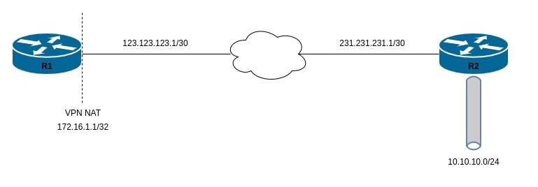
The topology for this guide is as below. We have 2 routers connected over an Internet connection and a VPN will be established and require the source (R1) to NAT all VPN traffic that gets sent to R2. The VPN will be use IKEv2 and PSKs for authentication.
First i'm going to configure the password that will be used for Pre-Shared Key for the IPSec peer. There are a couple of way sot do this, but I have chosen to use a keyring that allows me to specify multiple peers in order to be able to configure multiple IPSec tunnels and apply in a crypto map. To create a keyring, use the command crypto ikev2 keyring <name>. Once the keyring is created, you can specify a peer name and IP address along with the pre-shared key associated with that peer.
crypto ikev2 keyring POLICY-VPN
 peer R2
  address 231.231.231.1
  pre-shared-key mysecretpsk
Once you have the keyring created, you'll need to create the phase 1 crypto profile. For this profile, I'll be configuring the same settings as for the phase 2 so AES-256 and SHA256 with the DH group configured as 14 and a lifetime of 28800 seconds. These settings must match on the other side of the VPN configuration in order for it to work.
crypto isakmp policy 10
 encryption aes 256
 hash sha256
 authentication pre-share
 group 14
 lifetime 28800
Once you've configured the phase 1 settings, create the ikev2 profile that will be associated with the VPN peer. This profile will need to specify a few options including:
- Remote peer's IP VPN termination IP address
- Local routers VPN source IP address
- authentication type
- key lifetime settings
Like with most things IPSec related, these settings must match on the remote end as well. Note that the IP address specified in the match identity remote address command must match the peer IP specified in the crypto keyring in the previous step.
crypto ikev2 profile R2-PROFILE
 match identity remote address 231.231.231.1 255.255.255.255
 identity local address 123.123.123.1
 authentication remote pre-share
 authentication local pre-share
 keyring local POLICY-VPN
 lifetime 28800
Once you have the ikev2 profile and the keyring configured, now configure an ACL that will match the interesting traffic. This ACL should be configured to match and source and destination that should be encrypted and sent over the VPN. If your VPN is designed so that either the source or destination can initiate the VPN tunnel, then this ACL should match for both source and destination in reverse as below.
ip access-list extended RP-CRYPTO
permit ip 10.10.10.0 0.0.0.255 host 172.16.1.1
permit ip host 172.16.1.1 10.10.10.0 0.0.0.255
Once you have the keyring, crypto profile and your crypto ACL, it's time to create the crypto map itself. As i've already shown how to create a transform set in the previous route based VPN post I won't show that configuration here. Within the IPSec configuration, this is where you will specify the phase 2 options such as:
- peer IP
- SA lifte time
- SA idle time
- Encryption and Integrity settings
- DH Group
- The associated IKEv2 profile
- an ACL that matches the "Interesting" traffic
The following options are not really recommended these days and would actually be considered insecure however for a lab environment it is fine. If i was to actually configure this tunnel for a production environment, I would use a transform set that is at minimum AES 256 for authentication and integrity of SHA384. I would also set the DH group to a minimum of 16 and the SA lifetime would be reduced from 28800 to 14400.
crypto map IPSEC-VPN 1 ipsec-isakmp
 set peer 231.231.231.1
 set security-association lifetime seconds 28800
 set security-association idle-time 1800
 set transform-set AES-256-SHA256
 set pfs group14
 set ikev2-profile R2-PROFILE
 match address RP-CRYPTO
That's it for the IPSec configuration. The last step is to apply that configuration to an interface. This would normally be applied to your WAN interface which in my case is G0/0/0. To apply the crypto map to an interface, use the command crypto map <NAME>. If you are not configuring NAT over your VPN tunnel, then you're done. You should now be able to successfully establish a VPN tunnel and send and receive traffic to your remote peer. If you have a requirement for NAT to be configured then keep reading. As you have probably noticed, my WAN interface g0/0/0 has the ip nat outside command configured as I have a requirement to NAT my traffic outbound from my home network.
interface GigabitEthernet0/0/0
 ip nat outside
 crypto map IPSEC-VPN
In this lab the SVI vlan 100 is configured as the inside LAN subnet and therefor has the ip nat inside command applied. I have already configured an ip nat statement for my normal day to day traffic so the rest of this post will run through how to configure NAT over the IPSec VPN. In this case, the NAT configuration will be from the point of view of R1.
interface Vlan100
 ip address 10.1.1.1 255.255.255.0
 ip nat inside
In order to configure NAT for this scenario, you will need to use a combination of extended ACL's, and a route-map for your NAT configuration. The idea is to configure a deny rule on your existing NAT configuration to deny any VPN traffic from hitting that NAT rule, and create another ACL that will match your VPN traffic that should be NAT'ed before sending over the tunnel. To do that, I have created an ACL POL-VPN-NAT to match the specific VPN traffic which in this case is anything on the R1 LAN 10.1.1.0/24, going to 10.10.10.0/24. I have then added 2 deny statements to my PAT ACL that is applied to my nat overload command. These deny statements will deny any traffic that is associate with the VPN from being NAT'ed in that statement.
ip access-list extended POL-VPN-NAT
permit ip any 10.10.10.0 0.0.0.255

ip access-list extended PAT
deny ip any host 172.16.1.1
deny ip any 10.10.10.0 0.0.0.255
permit ip 10.1.1.0 0.0.0.255
With my ACL's configured, I now need to configure a route-map that will be used in the NAT statement to match and of the VPN traffic.
route-map POL-VPN-NAT permit 10
match ip address POL-VPN-NAT
With all the pieces of the puzzle ready, it's time to put it all together. The first line in the below output is my normal NAT overload command that is used for all outbound Internet traffic. As you can see, this has the PAT ACL applied so that the IPSec VPN traffic will not match and therefor not be NAT'ed. I then have a static NAT configuration applied as in this specific scenario, I want the host 10.1.1.15 , to be statically source NAT'ed with an IP of 172.16.1.1 when traversing the tunnel. You could configure it so that all of the LAN side traffic from 10.1.1.0/24 to 10.10.10.0/24 is source PAT'ed to 172.16.1.1 as well.
ip nat inside source list PAT interface GigabitEthernet0/0/0 overload
ip nat inside source static 10.1.1.15 172.16.1.1 route-map POL-VPN-NAT extendable
And that's it. That's a very basic example of how to configure a policy based VPN on Cisco routers. If you've noticed anything missing or have any issues with this post or just want to say Hi, please leave a comment and let me know.
Add new comment