Nexus 9k Virtual VXLAN LAB Part 1
This is going to be a multi part post on building your own VXLAN lab environment using ESXi and the Nexus 9k Virtual switches. This will be a very simple and small VXLAN Lab with 2 Leaf Switches, 1 Spine switch and a Border Gateway switch, but it will be enough to enable you to get your head around how VXLAN/BGP EVPN works and the benefits of it.
- Part 2: Underlay and VXLAN Configuration
- Part 3: VXLAN VRF Configuration
I'm wont be going through how to deploy a virtual switch in this series as I've already done that here. This series will only go through the actual configuration of ESXi and how to get the virtual switches to communicate. I will also go through how I went about getting the virtual machines to communicate on the network as though they are physically connected to Leaf Switches as well. The first part of this series, will run through configuring the actual virtual switches and getting basic connectivity, the second part will be for the underlay routing of the VLAN environment and the VXLAN configuration. The third part will fo through configuring VRF's inside the VXLAN environment.
For this LAB, I will be using the below topology. This is a simple VXLAN Lab environment with 2 leaf switches, 1 Spine switch, and 1 Border Gateway Switch. I have also configured an external virtual switch as the gateway to my physical network (WRLABCR01). This device doesn't participate in VXLAN in any way, it's simply there as a BGP peer to the rest of the world for the VXLAN environment.
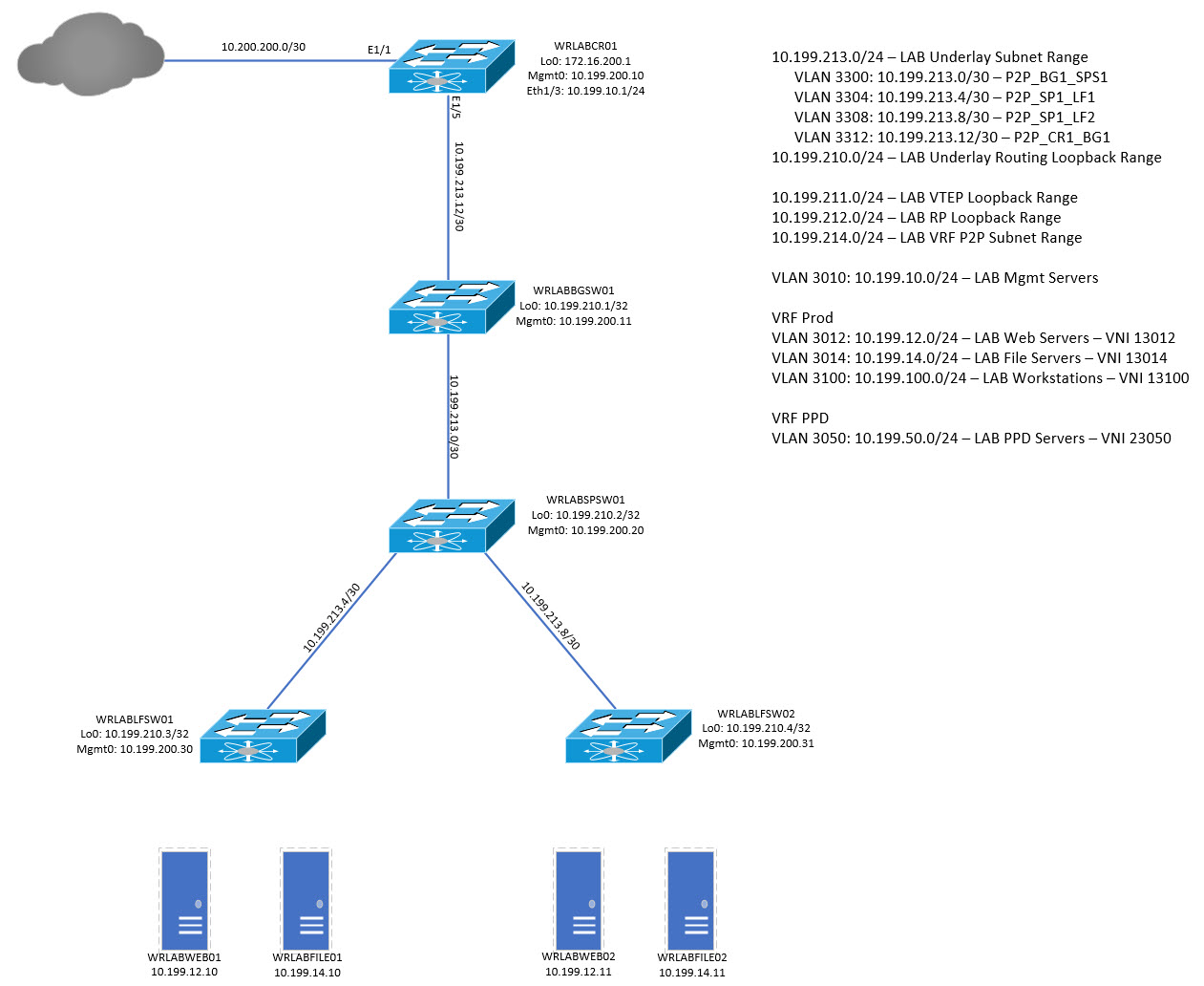
For physical device connectivity from the WRLABCR01 switch (if you're following the above topology) back to your physical network, see my blog post here. To begin, lets look at how to actually configure the virtual switches ready for the underlay connectivity. The first step is to create the required networks in ESXi. I will be using Vcentre Server do this but the configuration is the same if done directly on an ESXi host but the menu options might differ.
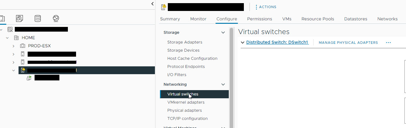
Because I'm not connecting these switches to my physical network and am isolating connectivity from the LAB servers to the rest of my network, I need to create a new virtual switch that has no physical interfaces attached to it. To do that, select the ESXi host, and click on the Configure tab. Under Networking, select Virtual Switches.
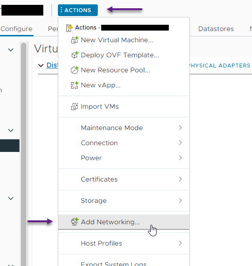
On the Virtual Switches tab, select ACTIONS and then select Add Networking.
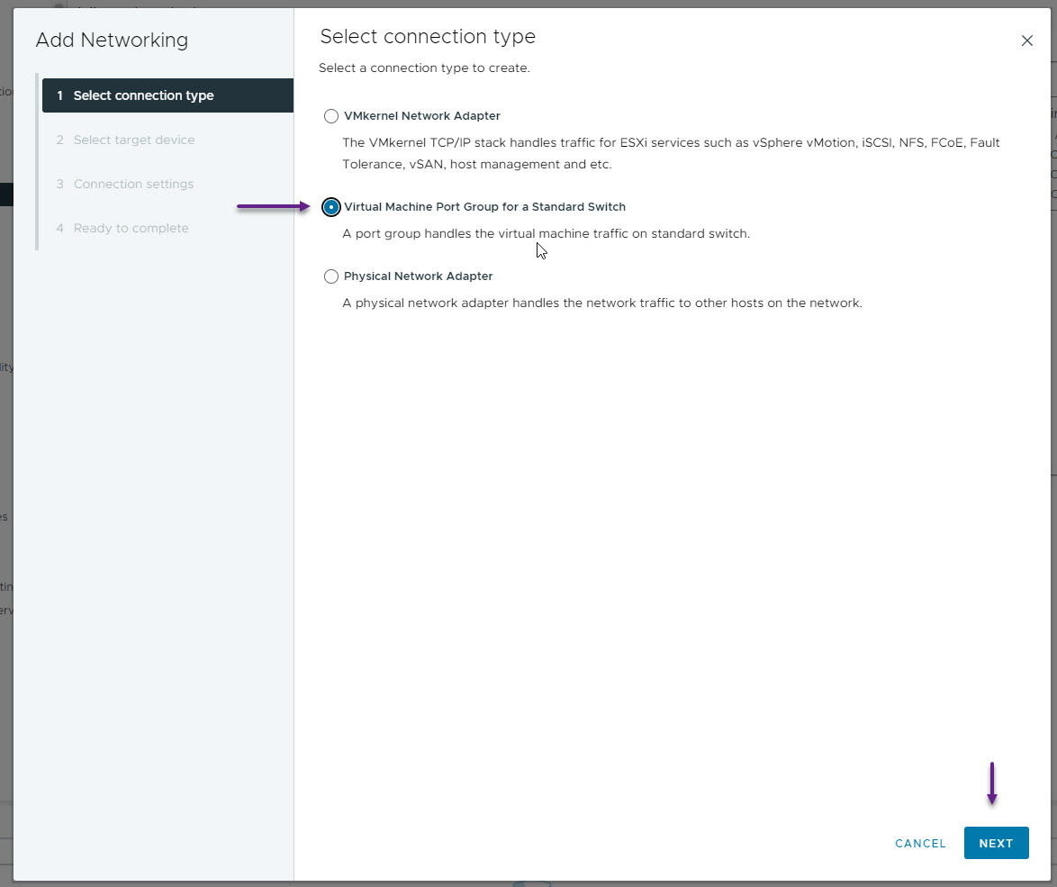
On the Select connection type page, select Virtual Machine Port Group for a Standard Switch and click Next.
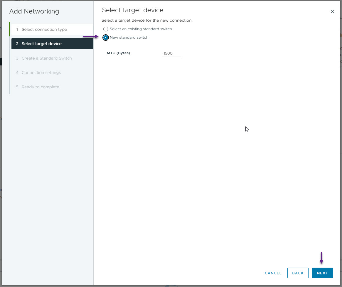
On the Select target device page, select New standard switch and click next.
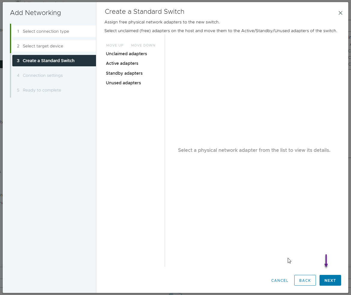
On the Create a Standard Switch page, don't add any physical interfaces if you have any available and click next.
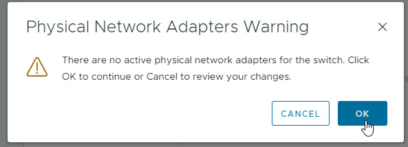
You will receive a warning about there being no physical network adapters, just click OK here as we don't want any for our LAB.
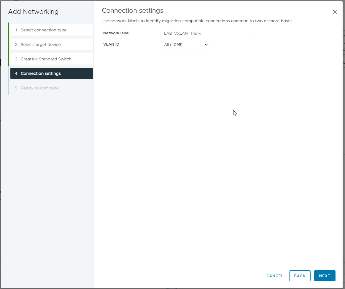
On the connection settings page give the network a label and configure it as a trunk by specifying the VLAN ID as 4095. Once done click next.
On the last page confirm the details and click Finish.

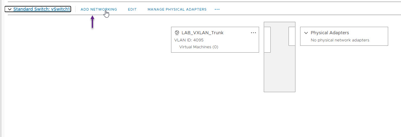
With the new virtual switch created, you now need to add all of your VLANs. To do that, select the new vSwitch, and click ADD NETWORKING.
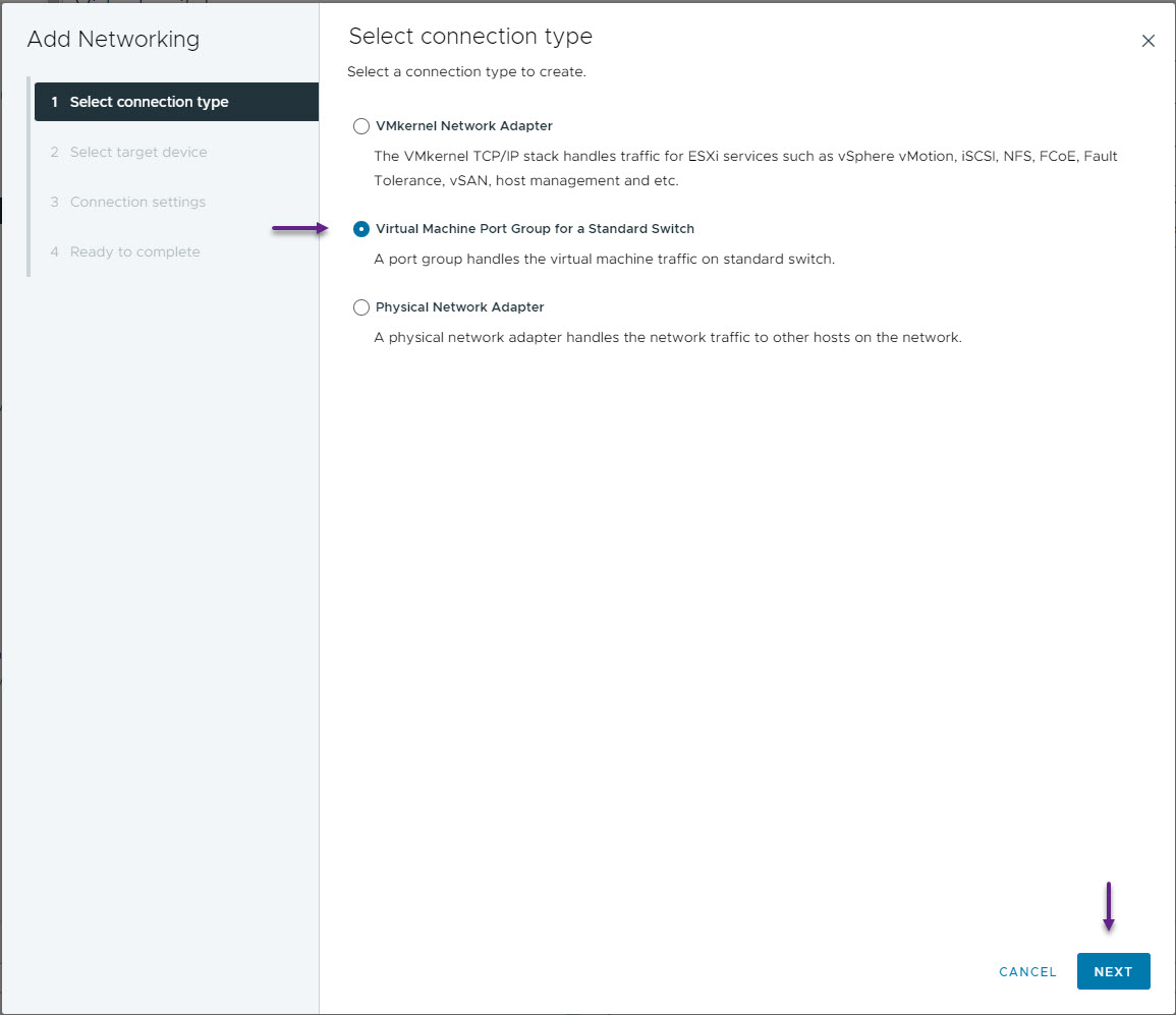
On the Select connection type, once again select Virtual Machine Port Group for a Standard Switch and click next.
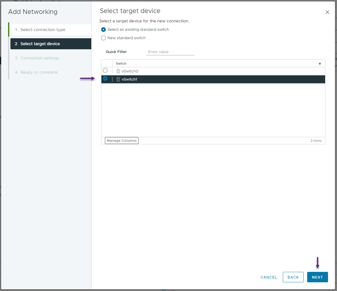
On the Select target device page, select the vSwitch that you created for your VXLAN fabric and click Next
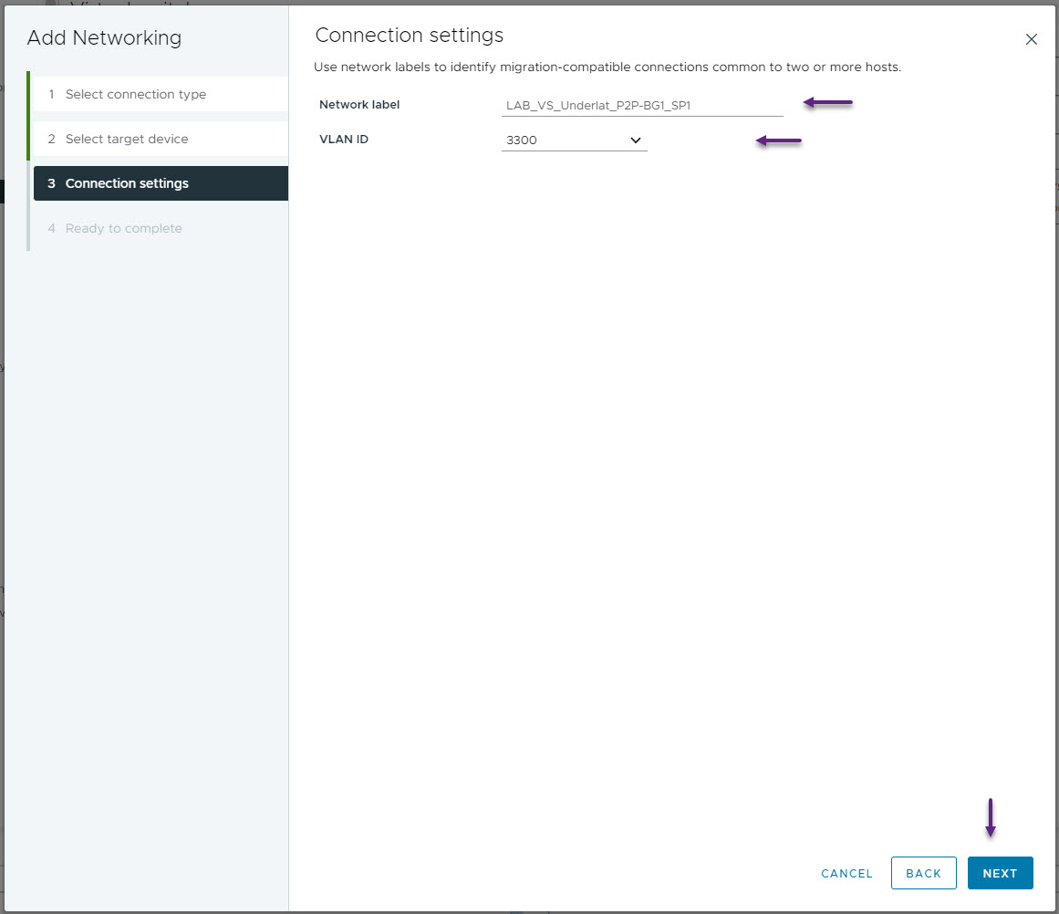
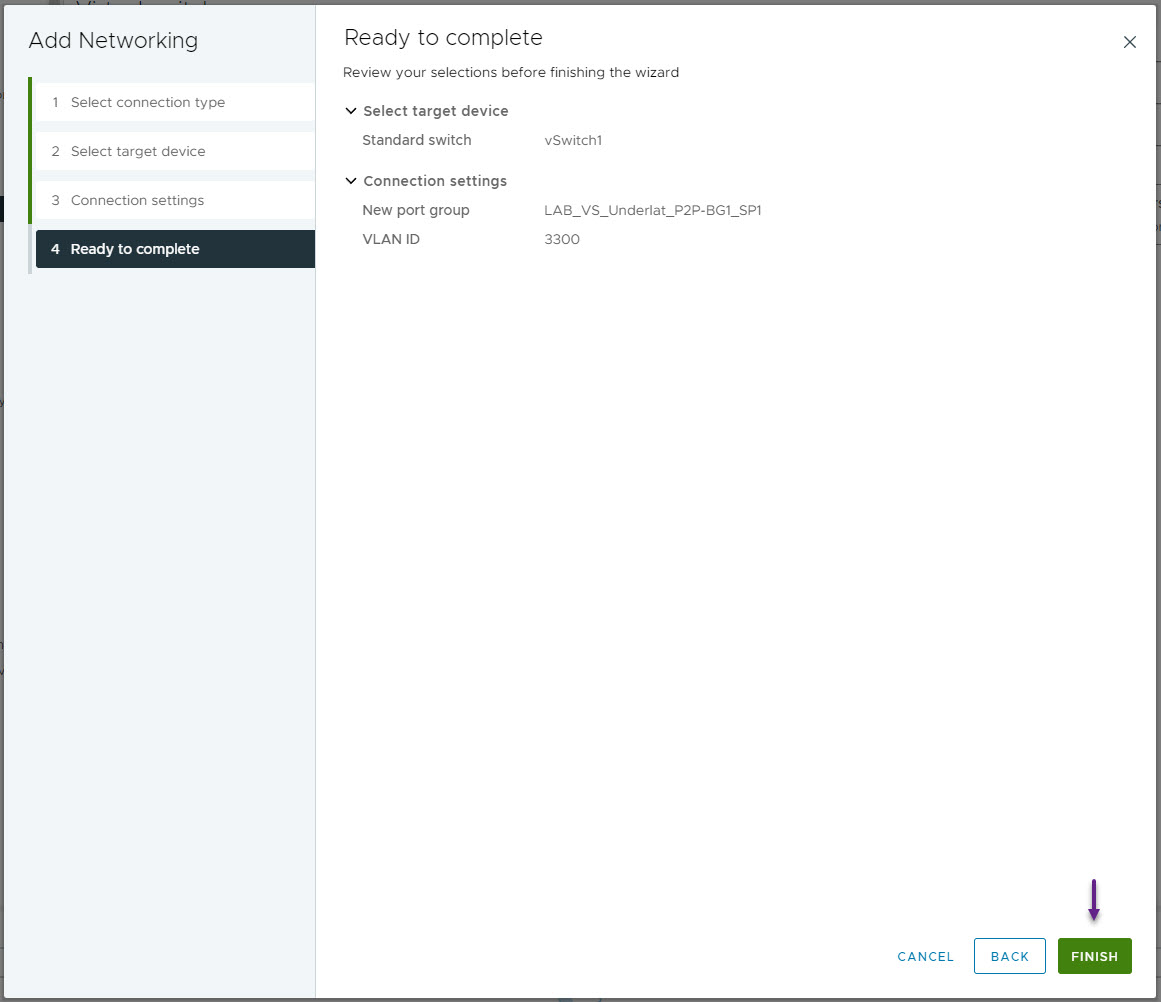
On the Connection settings page, give the network a name, and configure the VLAN ID. This network is for the Point to Point connection between WRLABBGSW01 and WRLABSPSW01.
On the Ready to complete page, confirm all of the settings are correct and click Finish.
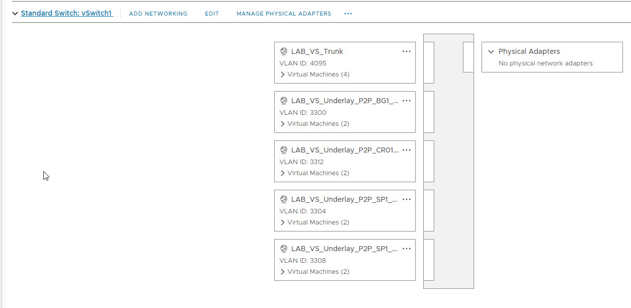
Repeat this for all of the required VLANs for your environment. As I will be doing the Server connectivity later, I've only configured the underlay VLAN's at this stage.
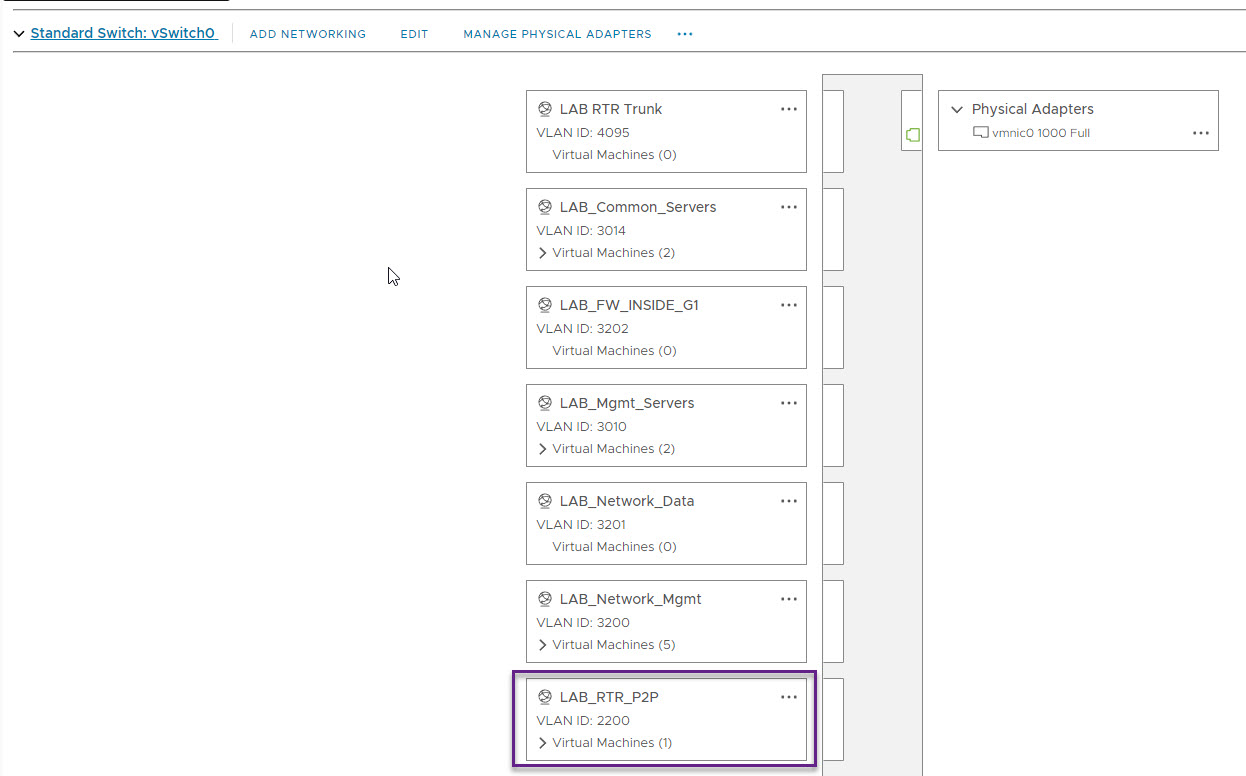
If you want to connect your virtual switches to your physical network as I have on WRLABCR01, you will need to create a VLAN for that as well, but create it on your vSwitch that has a physical adapted allocated. In my LAB VLAN 2200 is used to create a P2P link between the WRLABCR01 switch and the my physical Cisco Router.
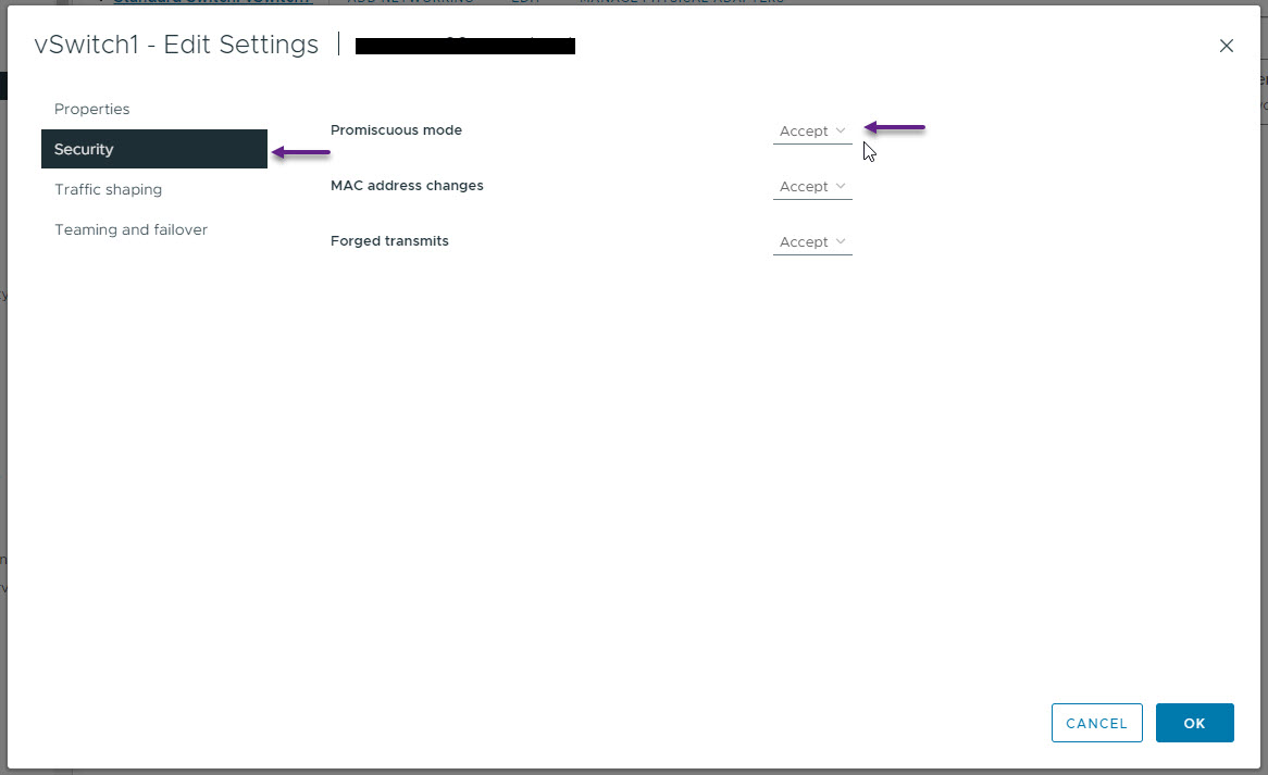
Once you have all of your VLANs created on the new vSwitch, you will need to enable some additional options in VMWare. Select the new vSwitch and click on EDIT.
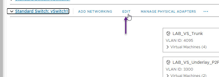
On the settings page, select Security and then set Promiscuous mode to Accept. Once done click OK. Without doing this, you will not be able to ping anything within your LAB environment.
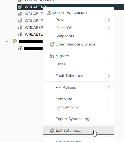
Now it's time to configure the actual virtual switch interfaces. I'll start by configuring the WRLABCR01 switch interfaces first. Right click on the virtual device and select Edit Setting.
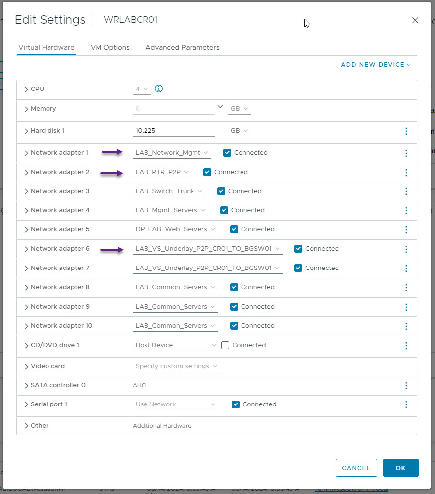
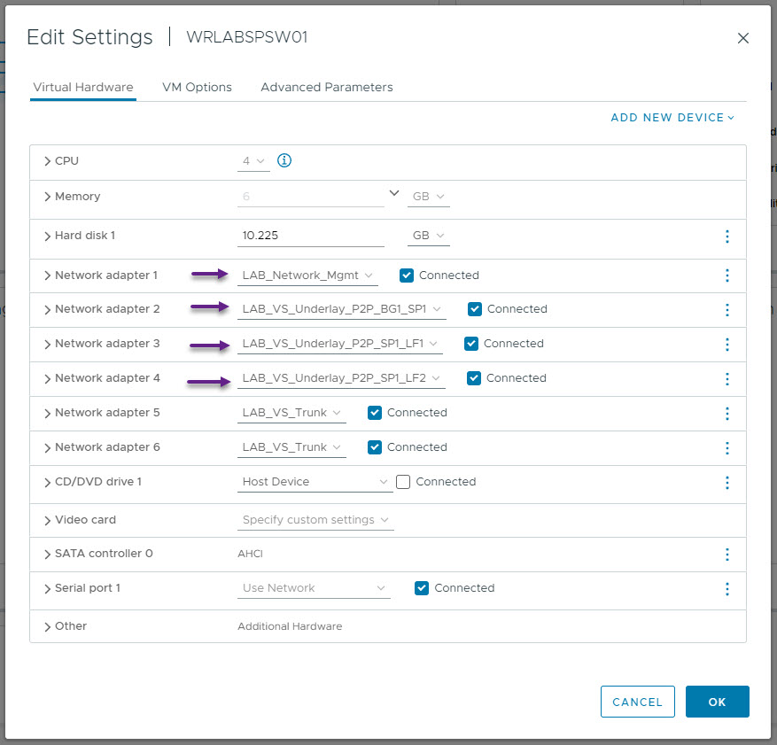
On my CR Switch I have some additional interfaces setup for other things so ignore those in the below screenshot and focus on the three interfaces I've indicated. Always remember that the first interface (Network adapter 1) is the management interface of the virtual switch so switch port eth1/1 relates to Network adapter 2 in VMWare and so on. As per the LAB design, I've configured eth1/1 on WRLABCR01 with the VLAN that connects to my physical network and the interface eth1/5 (Network adapter 6) to the VLAN on the new vSwitch to WRLABBGSW01. (I haven't actually yet been able to configure more than the first 5 interfaces on these virtual switches. The Cisco documentation says that you can have up to 64, but for some reason which I haven't worked out yet, only the first 5 ports will come up.)
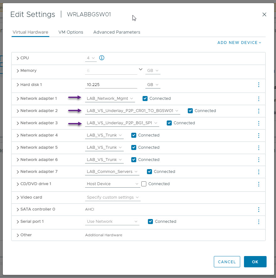
You will need to repeat the above process of allocating the virtual switch interfaces to the required VLANs on each of the virtual Nexus switches. The next switch I've configured is WRLABBGSW01. Once again configure the management interface, and the uplink interfaces to WRLABCR01 and WRLABSPSW01.
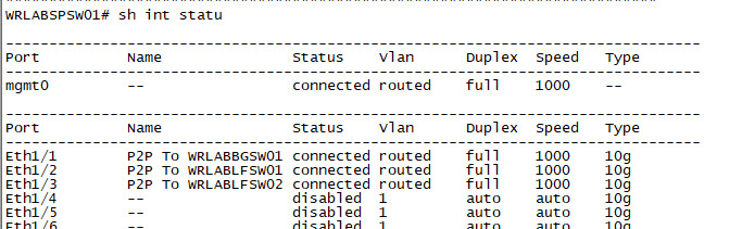
Next configure the Spine switch. The Spine switch will have an interface that connects to each of the leaf switches and the BG switch. In my lab WRLABSPSW01 eth1/1 connects to WRLABBGSW01, eth1/2 connects to WRLABLFSW01, and eth1/3 to WRLABLFSW02.
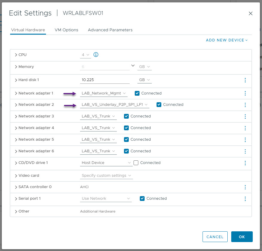
Now configure the interfaces on both Leaf Switch 1 and Leaf Switch 2. Leaf Switch 1 and 2 at the stage will only have one interface, Eth1/1, that connects to the Spine switch. The VM Interfaces will be configured later.
 |  |
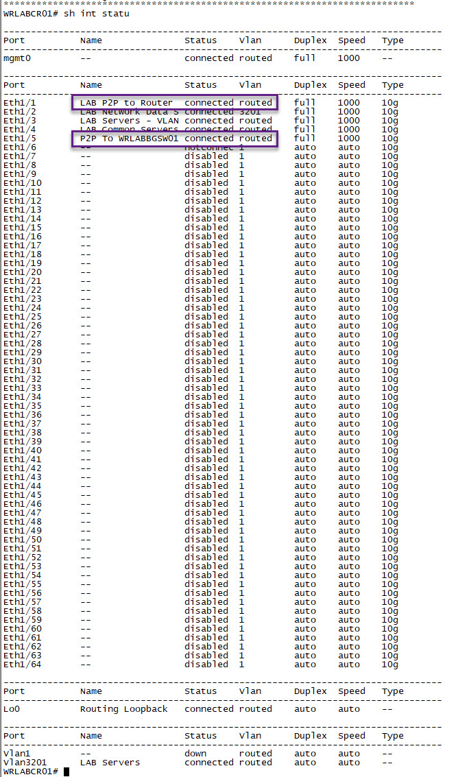
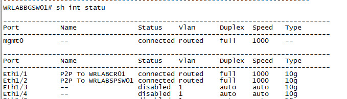
With that done, it's now time to start configuring the virtual switches. Once you have them booted, SSH into each one. I started with WRLABCR01. Because this swtich connects the my physical network, there is a trick to getting it to be able to actually talk to my physical devices. I won't go through that in detail here, but you will need to manually configure the Switch port with the MAC address of the interface from VMWare. Below is the output of sh int status on WRLABCR01. Take note of the Eth1/1 and Eth1/5 interface configuration here. These are the routed ports for Point to Point connectivity in and out of my LAB environment.
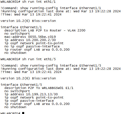
Below is the port configuration of Eth1/1 and Eth1/5. Note the MAC address configured on the switch port Eth1/1. This is the MAC address that is on the interface in VMware. This isn't required on Eth1/5, as that interface is connected to the LAB vSwitch. This lab uses OSPF for the underlay, but you can use any routing protocol you like. WRLABCR01 doesn't actually participate in the underlay routing though of the LAB, OSPF is configured for routing only because my actual network uses OSPF. My OSPF area 0 is configured my physical router and switch, and OSPF Area 200 is for connectivity from my physical network into me LAB environment. This is why OSPF area 200 is only configured on WRLABCR01 interfaces, and not on WRLABBGSW01. WRLABBGSW01 will participate in OSPF still, but only in the LAB Underlay environment.
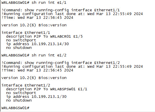
You will need to configure all of your interfaces, and ports on all of your lab switches. Below is the output of the interface configuration of WRLABBGSW01. Once again, I am using routed ports and there is no OSPF configuration yet in the LAB. This will be done in Part 2.
 |  |
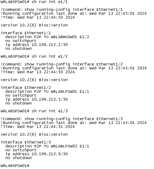
Now configure your Spine switch interfaces.
 |  |
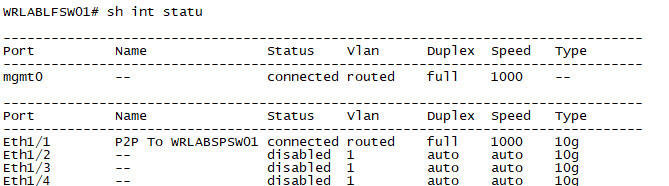
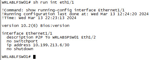
And lastly, Configure all of your Leaf Switch interfaces.
WRLABLFSW01
 |  |
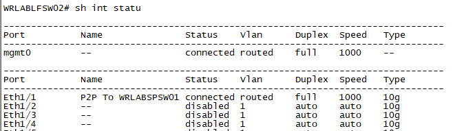
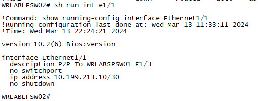
WRLABLFSW02
 |  |
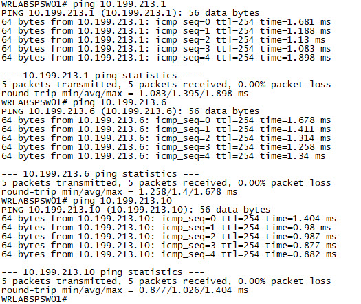
With all of the switch interfaces configured. You should now be able to ping each switch from the Spine Switch. You won't be able to ping between WRLABBGSW01 and either of the Leaf Switches yet as we haven't configured the Underlay routing.
That's it for Part 1. Part 2 will go through configuring the Underlay, and VXLAN. If you've noticed anything missing or have any issues with this post, please leave a comment and let me know.
Add new comment