Nexus 9k Virtual VXLAN LAB Part 2
If you've followed Part 1, you should now have your virtual switches configured, and be able to ping between the Spine switch, the Border Gateway switch, and Leaf Switches. Now it's time to start configuring the underlay routing and then VXLAN itself.
- Part 1: VMWare and Virtual Switch Configuration
- Part 3: VXLAN VRF Configuration
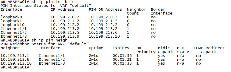
In Part 2 of this series, I'll go through configuring the OSPF Underlay, and configuring the beginnings of the VXLAN fabric itself. In the below diagram, WRLABCR01 is not part of the VXLAN fabric itself and is only a Gateway to the external network. This would simulate a device in a production environment that connects your VXLAN fabric to your other Datacentres, or even connecting 2 VXLAN Fabrics between DC's together. For this post, I will only be going through a basic configuration of VXLAN for 2 hosts in VLAN 3012. The rest of the configuration will come in part 3.
Before I begin with configuring the Underlay routing, there are some Nexus features that you will need to enable on all of the VXLAN switches in the environment. On each switch, enter configuration mode, and enable the following features.
# conf t
Enter configuration commands, one per line. End with CNTL/Z.
(config)# conf t
(config)# nv overlay evpn
(config)# feature ospf
(config)# feature bgp
(config)# feature ospfv3
(config)# feature pim
(config)# feature interface-vlan
(config)# feature vn-segment-vlan-based
(config)# feature nv overlay
With that done, The underlay routing for the VXLAN fabric requires some additional loopback interfaces on each device. Log into each device and create two additional loopback addresses. One loopback is for the OSPF Underlay, and the second is for the VXLAN Fabric VTEP.
WRLABBGSW01

WRLABBGSW01# conf t
Enter configuration commands, one per line. End with CNTL/Z.
WRLABBGSW01(config)#interface loopback0
WRLABBGSW01(config-if)#ip address 10.199.210.1/32
WRLABBGSW01(config-if)#interface loopback1
WRLABBGSW01(config-if)#description VTEP Loopback
WRLABBGSW01(config-if)#ip address 10.199.211.1/32


WRLABSPSW01

WRLABSPSW01# conf t
Enter configuration commands, one per line. End with CNTL/Z.
WRLABSPSW01(config)#interface loopback0
WRLABSPSW01(config-if)#ip address 10.199.210.2/32
WRLABSPSW01(config-if)#interface loopback1
WRLABSPSW01(config-if)#description VTEP Loopback
WRLABSPSW01(config-if)#ip address 10.199.211.2/32

WRLABLFSW01

WRLABLFSW01# conf t
Enter configuration commands, one per line. End with CNTL/Z.
WRLABLFSW01(config)#interface loopback0
WRLABLFSW01(config-if)#ip address 10.199.210.3/32
WRLABLFSW01(config-if)#interface loopback1
WRLABLFSW01(config-if)#description VTEP Loopback
WRLABLFSW01(config-if)#ip address 10.199.211.3/32

WRLABLFSW02

WRLABLFSW02# conf t
Enter configuration commands, one per line. End with CNTL/Z.
WRLABLFSW02(config)#interface loopback0
WRLABLFSW02(config-if)#ip address 10.199.210.4/32
WRLABLFSW02(config-if)#interface loopback1
WRLABLFSW02(config-if)#description VTEP Loopback
WRLABLFSW02(config-if)#ip address 10.199.211.4/32
With all of the required features enabled and loopback interfaces configured, you can now configure OSPF for the Underlay routing. The configuration is the same on each switch with the exception of the interfaces that OSPF needs to be enabled on. This lab will configure each device in a single OSPF area 0. There't no need to create additional areas inside a VXLAN fabric as this is used for the Underlay routing. Start by configuring OSPF on the Border Gateway switch. I am not enabling OSPF on the interface that goes from the Border Gateway switch to WRLABCR01.
WRLABBGSW01(config-if)# router ospf LAB
WRLABBGSW01(config-router)# router-id 10.199.210.1
WRLABBGSW01(config-router)# passive-interface default
WRLABBGSW01(config-router)# interface Ethernet1/2
WRLABBGSW01(config-if)#   ip ospf network point-to-point
WRLABBGSW01(config-if)#   ip router ospf LAB area 0.0.0.0
WRLABBGSW01(config-if)#   no ip ospf passive-interface
WRLABBGSW01(config-if)# interface loopback0
WRLABBGSW01(config-if)#   ip ospf network point-to-point
WRLABBGSW01(config-if)#   ip router ospf LAB area 0.0.0.0
WRLABBGSW01(config-if)# interface loopback1
WRLABBGSW01(config-if)#   ip router ospf LAB area 0.0.0.0
Next, configure OSPF on your Spine Switch.
WRLABSPSW01(config)# ip host WRLABBGSW01 10.199.210.1
WRLABSPSW01(config)# ip host WRLABLFSW01 10.199.210.3
WRLABSPSW01(config)# ip host WRLABLFSW02 10.199.210.4
WRLABSPSW01(config)# router ospf LAB
WRLABSPSW01(config-router)#   router-id 10.199.210.2
WRLABSPSW01(config-router)#   name-lookup
WRLABSPSW01(config-router)# interface Ethernet1/1
WRLABSPSW01(config-if)#   ip ospf network point-to-point
WRLABSPSW01(config-if)#   ip router ospf LAB area 0.0.0.0
WRLABSPSW01(config-if)# interface Ethernet1/2
WRLABSPSW01(config-if)#   ip ospf network point-to-point
WRLABSPSW01(config-if)#   ip router ospf LAB area 0.0.0.0
WRLABSPSW01(config-if)# interface Ethernet1/3
WRLABSPSW01(config-if)#   ip ospf network point-to-point
WRLABSPSW01(config-if)#   ip router ospf LAB area 0.0.0.0
WRLABSPSW01(config-if)# interface loopback0
WRLABSPSW01(config-if)#   ip ospf network point-to-point
WRLABSPSW01(config-if)#   ip router ospf LAB area 0.0.0.0
WRLABSPSW01(config-if)# interface Loopback1
WRLABSPSW01(config-if)#   ip router ospf LAB area 0.0.0.0
On the spine switch I configured OSPF slightly differently as I found this cool feature that the Nexus switches have where you can configure the host name and IP on it, then tell OSPF to do a name lookup. What this does, is when you do a sh ip ospf neigh on the switch, it shows you the hostname instead of the router-id. I only did this on the Spine switch though as all of the other devices only have a single neighbour anyway.
WRLABSPSW01# sh ip ospf ne
 OSPF Process ID LAB VRF default
 Total number of neighbors: 3
 Neighbor ID     Pri State            Up Time  Address         Interface
 WRLABBGSW01       1 FULL/ -          1w6d     10.199.213.1    Eth1/1
 WRLABLFSW01       1 FULL/ -          1w6d     10.199.213.6    Eth1/2
 WRLABLFSW02       1 FULL/ -          1w6d     10.199.213.10   Eth1/3
With the Border Gateway and Spine switches configured, next configure Leaf Switch 1.
WRLABLFSW01(config-if)#router ospf LAB
WRLABLFSW01(config-router)#router-id 10.199.210.3
WRLABLFSW01(config-router)#interface Ethernet1/1
WRLABLFSW01(config-if)#ip ospf network point-to-point
WRLABLFSW01(config-if)#ip router ospf LAB area 0.0.0.0
WRLABLFSW01(config-if)#interface loopback0
WRLABLFSW01(config-if)#ip address 10.199.210.3/32
WRLABLFSW01(config-if)#ip ospf network point-to-point
WRLABLFSW01(config-if)#ip router ospf LAB area 0.0.0.0
WRLABLFSW01(config-if)#interface loopback1
WRLABLFSW01(config-if)#description VTEP Loopback
WRLABLFSW01(config-if)#ip address 10.199.211.3/32
WRLABLFSW01(config-if)#ip router ospf LAB area 0.0.0.0
And lastly, configure Leaf Switch 2.
WRLABLFSW02(config-if)# router ospf LAB
WRLABLFSW02(config-router)#   router-id 10.199.210.4
WRLABLFSW02(config-router)# interface Ethernet1/1
WRLABLFSW02(config-if)#   ip ospf network point-to-point
WRLABLFSW02(config-if)#   ip router ospf LAB area 0.0.0.0
WRLABLFSW02(config-if)# interface loopback0
WRLABLFSW02(config-if)#   ip address 10.199.210.4/32
WRLABLFSW02(config-if)#   ip ospf network point-to-point
WRLABLFSW02(config-if)#   ip router ospf LAB area 0.0.0.0
WRLABLFSW02(config-if)# interface loopback1
WRLABLFSW02(config-if)#   description VTEP Loopback
WRLABLFSW02(config-if)#   ip address 10.199.211.4/32
WRLABLFSW02(config-if)#   ip router ospf LAB area 0.0.0.0
With OSPF out of the way, you should now see all of your underlay routes in the route table. As the spine switch connects to each device in the VXLAN fabric, if you do a show ip ospf neighbor you should see all of your devices listed as neighbours, and all of your routes in the output of the sh ip route ospf command.
WRLABSPSW01# sh ip ospf ne
 OSPF Process ID LAB VRF default
 Total number of neighbors: 3
 Neighbor ID     Pri State            Up Time  Address         Interface
 WRLABBGSW01       1 FULL/ -          1w6d     10.199.213.1    Eth1/1
 WRLABLFSW01       1 FULL/ -          1w6d     10.199.213.6    Eth1/2
 WRLABLFSW02       1 FULL/ -          1w6d     10.199.213.10   Eth1/3

 WRLABSPSW01# sh ip route ospf
IP Route Table for VRF "default"
'*' denotes best ucast next-hop
'**' denotes best mcast next-hop
'[x/y]' denotes [preference/metric]
'%<string>' in via output denotes VRF <string>

10.199.210.1/32, ubest/mbest: 1/0
    *via 10.199.213.1, Eth1/1, [110/41], 1w6d, ospf-LAB, intra
10.199.210.3/32, ubest/mbest: 1/0
    *via 10.199.213.6, Eth1/2, [110/41], 1w6d, ospf-LAB, intra
10.199.210.4/32, ubest/mbest: 1/0
    *via 10.199.213.10, Eth1/3, [110/41], 1w6d, ospf-LAB, intra
10.199.211.1/32, ubest/mbest: 1/0
    *via 10.199.213.1, Eth1/1, [110/41], 1w6d, ospf-LAB, intra
10.199.211.3/32, ubest/mbest: 1/0
    *via 10.199.213.6, Eth1/2, [110/41], 1w6d, ospf-LAB, intra
10.199.211.4/32, ubest/mbest: 1/0
    *via 10.199.213.10, Eth1/3, [110/41], 1w6d, ospf-LAB, intra
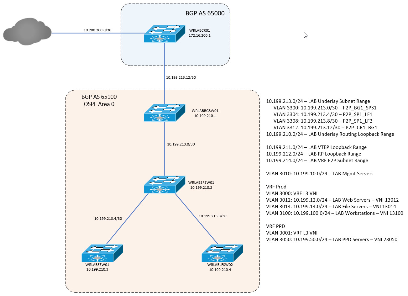
You can confirm connectivity by logging into one of the Leaf Switches, and trying to ping the loopback on your Border Gateway switch.
With the Underlay configured, it's time to start configuring the VXLAN overlay. Because VXLAN utilises mutlicast, you need to enable and configure multicast routing. The Spine switch in this lab (WRLABSPSW01) will be configured as the Anycast RP (Rendevous Point). For this lab, I am using SSM for the multicast routing however you can use other ASM as well. To configure the Spine switch as the RP, first configure the Loopack RP interface and enable OSPF on the interface. Once configured and OSPF is enabled, configure the ip pim anycast address. For the anycast address, 10.199.212.2 is the RP loopback IP, and 10.199.210.2 is the Spine switches routing Underlay loopback IP. You will also need to configure the pim rp-address group range. This specifies the multicast address range associated with the RP.
WRLABSPSW01(config)# int lo10
WRLABSPSW01(config-if)# descr RP Loopback
WRLABSPSW01(config-if)# ip addr 10.199.212.2/32
WRLABSPSW01(config-if)# ip router ospf LAB area 0.0.0.0
WRLABSPSW01(config-if)# ip pim spar
WRLABSPSW01(config-if)# ip pim anycast-rp 10.199.212.2 10.199.210.2
WRLABSPSW01(config)# ip pim rp-address 10.199.212.2 group-list 224.0.0.0/4
Once multicast is configured, you need to enable multicast traffic on all interfaces that require it. In the VXLAN environment, that's pretty much every interface that connects to the Fabric and all loopback interfaces. If you're following my lab, you will need to enable ip pim sparse-mode on the Border Gateway, Spine, and Leaf switches on the following interfaces.
WRLABSPSW01
WRLABSPSW01# conf t
Enter configuration commands, one per line. End with CNTL/Z.
WRLABSPSW01(config)# int lo0,lo1,lo10
WRLABSPSW01(config-if)# ip pim sparse-mode
WRLABSPSW01(config-if)# int eth1/1,eth1/2,eth1/3
WRLABSPSW01(config-if-range)# ip pim sparse-mode
WRLABBGSW01
WRLABBGSW01# conf t
Enter configuration commands, one per line. End with CNTL/Z.
WRLABBGSW01(config)# int lo0,lo1
WRLABBGSW01(config-if)# ip pim spar
WRLABBGSW01(config-if)# int eth1/2
WRLABBGSW01(config-if)# ip pim spar
WRLABLFSW01
WRLABLFSW01# conf t
Enter configuration commands, one per line. End with CNTL/Z.
WRLABLFSW01(config)# int lo0,lo1
WRLABLFSW01(config-if)# ip pim spar
WRLABLFSW01(config-if)# int eth1/1
WRLABLFSW01(config-if)# ip pim spar
WRLABLFSW02
WRLABLFSW02# conf t
Enter configuration commands, one per line. End with CNTL/Z.
WRLABLFSW02(config)# int lo0,lo1
WRLABLFSW02(config-if)# ip pim spar
WRLABLFSW02(config-if)# int eth1/1
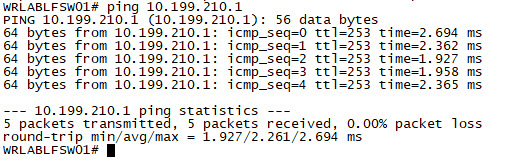
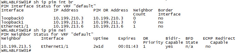
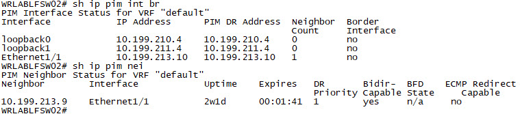
WRLABLFSW02(config-if)# ip pim sparWith the Multicast configuration complete on all switches, you should now be able to verify the pim neighbour relationship and multicast interface configuration. Log into all of your switches, and use the command sh ip pim int brief and sh ip pim neighbor to verify.
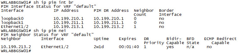 |  |
 |  |
Now it's time to start configuring VXLAN itself. VXLAN traffic is forwarded inside tunnels between VTEPs (Virtual Tunnel End-Points). VTEPs, are part of the Underlay and the tunnel entry and exit interfaces are called NVE (Network Virtualisation Edge) interfaces. Each of the Leaf switches, and the Border Gateway switches, will be configured with an NVE interface as these are the endpoints that VXLAN traffic will enter and exit. The Spine switch does not require an NVE interface. The NVE interfaces is what is used to map the VLAN to the VNI (Virtual Network Identifier) and send the VXLAN traffic. There can be layer 2 and layer 3 VNI's. For now I will only configure layer 2 VNI's and will go through the Layer 3 VNI's in Part 3 but for now, just know that the different VNI types are basically exactly how they sound. Think of a Layer 2 VNI as a VLAN, and a Layer 3 VNI, as an SVI that can be routed except Layer 3 VNI's, don't actually require an IP address.
Each NVE interface on the Leaf Switches and the Border Gateway switch, should be configured with a source interface of the VTEP Loopback interface.
WRLABBGSW01

WRLABBGSW01(config)# interface nve1
WRLABBGSW01(config-if-nve)# no shutdown
WRLABBGSW01(config-if-nve)# source-interface loopback1

WRLABLFSW01

WRLABLFSW01(config)# interface nve1
WRLABLFSW01(config-if-nve)# no shutdown
WRLABLFSW01(config-if-nve)# source-interface loopback1

WRLABLFSW02

WRLABLFSW02(config)# interface nve1
WRLABLFSW02(config-if-nve)# no shutdown
WRLABLFSW02(config-if-nve)# source-interface loopback1
The next step is to configure your endpoint VLANs and the associated VNIs. If you're following this lab, I have several tiny core Linux VMs but for this part of the Lab, I'm only going to configure the two VMs in VLAN 3012, I'll configure the other VMs in part 3 as they require VXLAN routing to be configured. I will however configure the VLANs and VNI for each VLAN in the VRF-Prod VRF now (Note I'm not configuring the VRF yet as it's not required here). In my LAB design, I have three VLANs for end hosts, VLAN 3012, 3014 and 3100. Each of the VLANs are associated with the VNI's, 13012, 13014 and 13100 respectively. To begin, create the VLANs, and allocate the vn-segments, to the VLAN's themselves. This will need to be done only on your Leaf Switches. You will receive an error about double-wide arp-ether carving, you can ignore this as it's a virtual switch.
WRLABLFSW01

WRLABLFSW01(config-if-nve)# vlan 3012
WRLABLFSW01(config-vlan)#   name VNI_13012
WRLABLFSW01(config-vlan)#   vn-segment 13012
WRLABLFSW01(config-vlan)# vlan 3014
Warning: Enable double-wide arp-ether tcam carving if igmp snooping/Hsrp over vxlan is enabled. Ignore if tcam carving is already configured.
WRLABLFSW01(config-vlan)#   name VNI_13014
WRLABLFSW01(config-vlan)#   vn-segment 13014

WRLABLFSW02

WRLABLFSW02(config-if-nve)# vlan 3012
WRLABLFSW02(config-vlan)#   name VNI_13012
WRLABLFSW02(config-vlan)#   vn-segment 13012
WRLABLFSW02(config-vlan)# vlan 3014
Warning: Enable double-wide arp-ether tcam carving if igmp snooping/Hsrp over vxlan is enabled. Ignore if tcam carving is already configured.
WRLABLFSW02(config-vlan)#   name VNI_13014
WRLABLFSW02(config-vlan)#   vn-segment 13014
I would like to mention here that the VLAN doesn't need to actually match on both switches, but the VNI does. This means that you could have vlan 100 on one switch map to VNI 10000, and VLAN 500 on another switch map to VNI 10000 as well. While it's doable, for obvious reasons, it's not recommended.
With the VNI's configured, you need to enable them on the NVE interfaces otherwise you won't be able to send or receive an VXLAN traffic. When configuring the VNI's on the NVE interface, you also need to specify the multicast group address for that VNI. You can have the same multicast group configured for each VNI for simplicity, but depending on the scale/design of your VXLAN fabric, that might not be ideal. In VXLAN, multicast is used for your BUM traffic as well. Using Multicast for this means that only switches that have hosts in that VNI, should then receive that traffic. If all VNI's were allocated to the same multicast group address, then all switches would receive all BUM traffic regardless of if there were any hosts on that Switch in that VNI/VLAN. In this LAB, i've configured different multicast groups for each VNI so if there are no hosts on a Leaf switch in that VNI/VLAN, then it will not join that multicast group and therefor won't receive any unnecessary BUM traffic.
WRLABLFSW01

WRLABLFSW01(config-vlan)# interface nve1
WRLABLFSW01(config-if-nve)# member vni 13012
WRLABLFSW01(config-if-nve-vni)# mcast-group 239.0.0.12
WRLABLFSW01(config-if-nve-vni)# member vni 13014
WRLABLFSW01(config-if-nve-vni)# mcast-group 239.0.0.14

WRLABLFSW02

WRLABLFSW02(config-vlan)# interface nve1
WRLABLFSW02(config-if-nve-vni)# member vni 13012
WRLABLFSW02(config-if-nve-vni)# mcast-group 239.0.0.12
WRLABLFSW02(config-if-nve-vni)# member vni 13014
WRLABLFSW02(config-if-nve-vni)# mcast-group 239.0.0.14
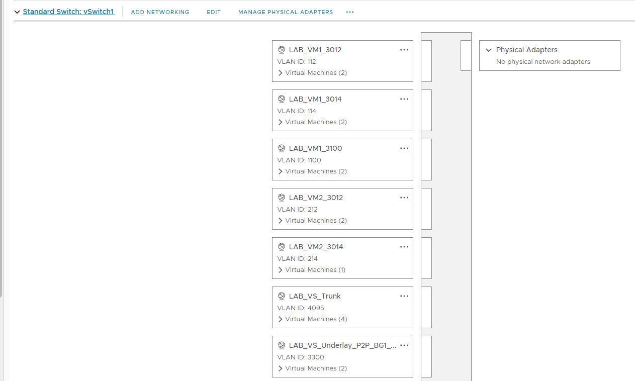
Okay, so now you have a very basic VXLAN configuration for 2 VLAN's. You should now be able to connect two virtual hosts to the Leaf switches, give them an IP address, and have them ping each other provided they're in the same VLAN. To mimic this, in vCenter, I created a couple more networks with fake VLAN's to allocate to the Virtual switch ports to mimic connecting to an access port. I have created enough VLAN's for 5 VM's and configured different VLAN's for each. This should be done on the vSwitch that was created for the VXLAN Fabric.
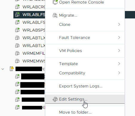
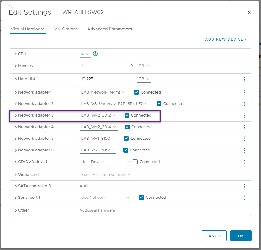
With the networks created, I then configured the interfaces on the Leaf Switches so that Eth1/2 was allocated to a VM. To do that, right click on the Virtual Switch and select Edit Settings.
On the settings page, Select Network Adapter 3 (Eth1/2), and allocate the network for the first VM and click save.

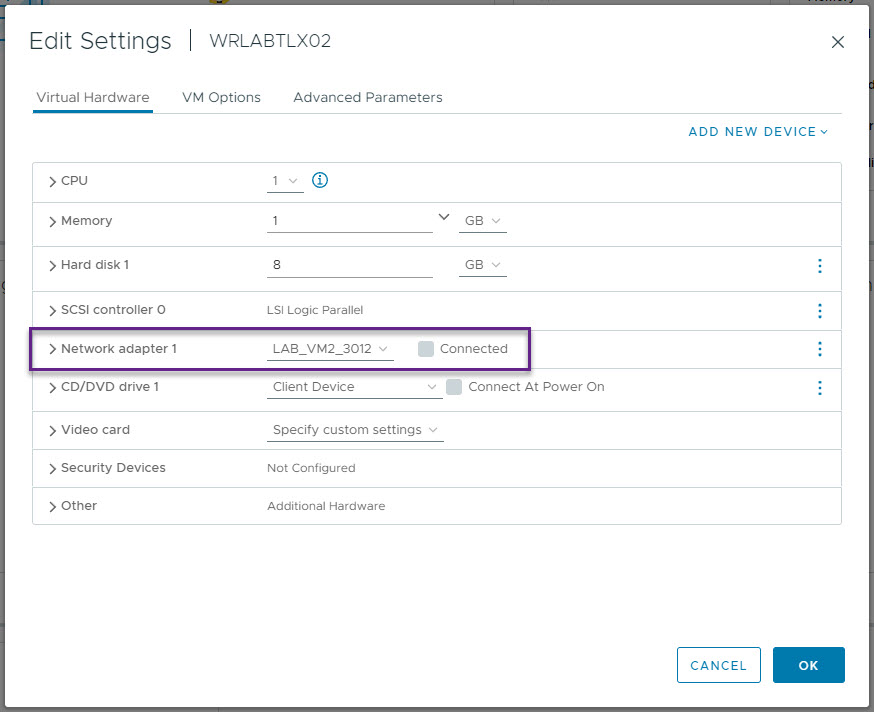
Now right click on your host VM, and click Edit settings, and then on the correct Network Adapter, select the same VM Network as allocated to the switch port. Once done, click save.
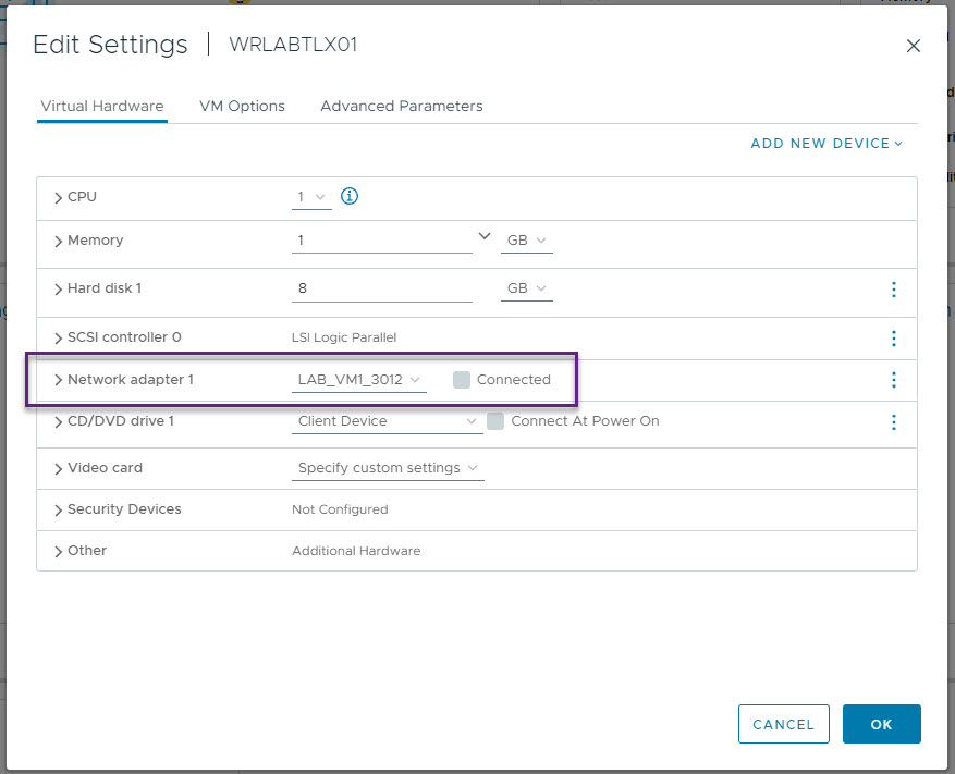
Repeat the above process for the second VM and VM Network for Leaf Switch 2 and host VM 2.
 |  |
Now boot your host VM's and if like me you're using Tiny Core Linux, you will need to configure an IP address and default gateway on them. Once that's done, you should be able to ping the VM's. My host IP's are 10.199.12.10 and 10.199.12.11.
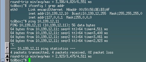
I would like to say that I did have a lot of trouble in my virtual environment getting this to work and to be honest, I'm not sure what changed as I turned off my lab overnight and checked again in the morning and it was working so don't worry if this doesn't work for you as the next step is to configure VXLAN routing to enable inter-vlan connectivity for your end hosts which is the end goal anyway. Just know that this should work and in a physical environment would have no issues.
VXLAN still requires an arp message to be sent out to locate hosts on the VXLAN fabric that it doesn't know about. These ARP messages, are encapsulated in a VXLAN header, and sent via multicast to each of the VTEPs in that multicast group. This still mean that VXLAN relies on flood and learn methods to locate end hosts just like a traditional network. This is where BGP EVPN comes in. BGP EVPN is a way for VTEPs to advertise their connected host details to all of the other VTEPs in the fabric including the host IP and MAC, and the VTEP it's attached to all using BGP.
Part 3 of this series will go into what's required to enable layer 3 symmetric routing between VXLAN segments and VRFs using BGP EVPN.
If you've noticed anything missing or have any issues with this post, please leave a comment and let me know.
Add new comment